
Specifications


ESS Technology, Inc. SAM0023-122898 13
ES1869 DATA SHEET
DIGITAL AUDIO
DIGITAL AUDIO
The ES1869 incorporates two digital audio channels.
There are three sources of DMA requests and three
targets for DMA acknowledge:
Audio 1 The first audio channel. This channel is used for
Sound Blaster Pro compatible DMA, Extended
mode DMA, and programmed I/O. It can be used
for either record or playback. Ideally, this
channel should be assigned to ISA channel 1.
Audio 2 The second audio channel. This channel is used
for audio playback in full-duplex mode. This
channel can be mapped to any of the three 8-bit
ISA DMA channels: 0,1, or 3.
External GPO1 can be assigned to be a DMA
acknowledge output, GPI can be used as a DMA
request input from an external device; either
CD-ROM, Modem, or general-purpose device.
This channel can be mapped to any of the four
DRQ/DACK pairs.
The three DMA sources are mapped to the four DMA pin
pairs by Plug and Play (PnP) registers. Also, the four DMA
pin pairs are assigned ISA DMA channel numbers by
Vendor-Defined Card-Level registers 23h and 24h. At
least two of the four pin pairs must be assigned to 8-bit ISA
DMA channels (0,1, or 3). The other one or two of the four
pin pairs can be assigned to one of the 16-bit ISA DMA
channels (5, 6, or 7) for use by the external DMA source.
In order for a DRQ output pin to be driving (as opposed to
high-impedance), two conditions must be met:
• The PnP register for the DMA of a given device must
match the ISA DMA channel number of the pin.
• The given device must be activated; that is, bit 0 of
PnP register 30h must be high.
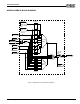
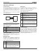
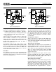
Figure 6 Data Transfer Modes
Programming DMA Transfers
Programming data transfers can be complicated with the
ES1869. Both Compatibility and Extended modes offer a
variety of modes for conducting transfers. The commands
to enable the different transfers vary depending on which
DMA channel and which mode (Compatibility or
Extended) is used.
The biggest difference in available data transfer modes is
between audio channel 1 and audio channel 2. This is
illustrated in Figure 6. Audio 2 only allows for DMA mode.
Audio 1 allows for Direct mode and DMA mode when
using Compatibility mode, and for programmed I/O and
DMA mode when using Extended mode.
Data Formats
See “Data Formats” on page44.
DMA Transfers in Compatibility Mode
The first audio channel is programmed using standard
Sound Blaster compatible commands. These commands
are written to the chip through port Audio_Base+Ch.
When programming the first audio channel for transfers,
one of the following modes can be used:
• Direct mode
• DMA modes
– Normal
– Auto-Initialize
In addition, both DMA Normal mode and DMA Auto-
Initialize mode can use a special High-Speed mode.
Direct Mode
In Direct mode, timing for DMA transfers is handled by the
application program. For example, the system timer can
be reprogrammed to generate interrupts at the desired
sample rate. At each system timer interrupt, the command
10h, 11h, 20h, or 21h is issued followed by the sample.
Polling of the Write-Buffer-Available flag (Audio_Base+Ch
[bit 7]) is required before writing the command and
between writing the command and the data.
NOTE: The switched capacitor filter is initialized by reset
for an intended sample rate of 8 kHz. In Direct mode, the
application may wish to adjust this filter appropriate to the
actual sample rate. Do this by programming the timer with
command 40h just as if the application were using DMA
mode.
DMA Modes
In DMA mode, the programmable timer in the ES1869
controls the rate at which samples are sent to the CODEC.
The timer is programmed using command 40h, which also
sets up the programmable filters inside the ES1869. The
ES1869 firmware maintains an internal FIFO (32 levels for
16-bit transfers, 64 levels for 8-bit transfers) that is filled by
DMA transfers and emptied by timed transfers to the DAC.
Digital Audio
Audio 1
Audio 2
Compatibility
Mode
Extended
Mode
Direct
Mode
DMA
Mode
ProgrammedDMA
Mode I/O
DMA
Mode
External