
Quick Start Guide


ESPRESSObin Ultra- Quick Start Guide page: 5 /24
5 / 24
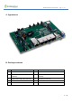
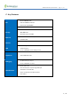
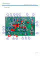
2. Top Side connectors and parts
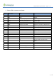
No. Part location Description 1 Description 2
1 SW2 Power Switch With LED indication
2 J11/ J3/ J10 MPP1_7/MPP1_6/MPP1_5 Boot Mode selection *see section F-1
3 BAT1 CR2032 /3V battery Power for Real Time Clock
4 J1 JTAG Debugger (not populated) 5x2 pins, *see section E-1
5 LED6 Yellow color MPP1_14 Software-driven (3.3V)
6 LED5 Red color MPP1_13 Software-driven (3.3V)
7 LED4 Green color MPP1_12 Software-driven (3.3V)
8 LED3 Blue color MPP1_11 Software-driven (3.3V)
9 LED1 Green color M.2 SSD LED (3.3V) connected to J6
10 M1 WiFi module
8.2.11/a/b/g/n/ac 2T2R WIFI
PCIe M.2 type 1216
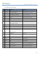
11 M1 Antenna WiFi Ant_B U.FL Micro coaxial connector 2.0mmx 2.0mm
12 M1 Antenna WiFi Ant_A U.FL Micro coaxial connector 2.0mmx 2.0mm
13 J6 SATA SSD connector M.2-22mmx 80mm
14 LED2 Green color USIM LED (3.3V) connected to J9
15 U39 USB2.0/ 4-port HUB
16 U4 SDRAM Rank2 16bit DDR4
18 J7 USB3.0 type A
18 J8 USB2.0 type A Downstream from U39 USB HUB
19 J12-D RJ45 1Gb RJ45-LAN#4
20 J12-C RJ45 1Gb RJ45-LAN#3
21 J12-B RJ45 1Gb RJ45-LAN#2
22 J12-A RJ45 1Gb RJ45-LAN#1
23 U45 Gb ethernet switch 6-port switch to J12-A/B/C/D and J17
24 J17 RJ45 with POE 1Gb RJ45 for WAN / POE power IN
25 J15 DC jack for 12VDC in Center positive 2.1mm diameter
26 M2 POE module DC12V/30W output, 802.3at/ 802.3af compliant