
Data Sheet
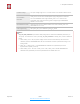
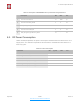
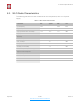
Table Of Contents
- Overview
- Wi-Fi Key Features
- Specifications
- Applications
- CPU, Memory, and Flash
- Clock
- Radio
- Wi-Fi
- Power Management
- General Purpose Input/Output Interface (GPIO)
- Secure Digital Input/Output Interface (SDIO)
- Serial Peripheral Interface (SPI/HSPI)
- I2C Interface
- I2S Interface
- Universal Asynchronous Receiver Transmitter (UART)
- Pulse-Width Modulation (PWM)
- IR Remote Control
- ADC (Analog-to-Digital Converter)
- Electrical Characteristics
- RF Power Consumption
- Wi-Fi Radio Characteristics
- Must-Read Documents
- Must-Have Resources

$
4. Peripheral Interface
frequency is 1 kHz, the duty ratio will be 1/22727, and a resolution of over 14 bits will be
achieved at 1 kHz refresh rate.
4.8. IR Remote Control
ESP8266EX currently supports one infrared remote control interface. For detailed pin
definitions, please see Table 4-8 below.
The functionality of Infrared remote control interface can be implemented via software
programming. NEC coding, modulation, and demodulation are supported by this interface.
The frequency of modulated carrier signal is 38 kHz, while the duty ratio of the square wave
is 1/3. The transmission range is around 1m which is determined by two factors: one is the
maximum current drive output, the other is internal current-limiting resistance value in the
infrared receiver. The larger the resistance value, the lower the current, so is the power, and
vice versa.
4.9. ADC (Analog-to-Digital Converter)
ESP8266EX is embedded with a 10-bit precision SAR ADC. TOUT (Pin6) is defined as
below:
The following two measurements can be implemented using ADC (Pin6). However, they
cannot be implemented at the same time.
•
Measure the power supply voltage of VDD3P3 (Pin3 and Pin4).
•
Measure the input voltage of TOUT (Pin6).
Table 4-8. Pin Definitions of IR Remote Control
Pin Name
Pin Num
IO
Function Name
MTMS
9
IO14
IR TX
GPIO5
24
IO 5
IR Rx
Table 4-9. Pin Definition of ADC
Pin Name
Pin Num
Function Name
TOUT
6
ADC Interface
Hardware Design
TOUT must be floating.
RF Initialization Parameter
The 107th byte of esp_init_data_default.bin (0 ~ 127 bytes), vdd33_const must
be set to 0xFF.
RF Calibration Process
Optimize the RF circuit conditions based on the testing results of VDD3P3 (Pin3
and Pin4).
User Programming
Use system_get_vdd33 instead of system_adc_read.
Espressif
$ /$ 17 26
Submit Documentation Feedback
2020.10