
Data Sheet

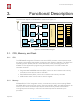

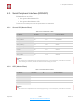

Table Of Contents
- Overview
- Wi-Fi Key Features
- Specifications
- Applications
- CPU, Memory, and Flash
- Clock
- Radio
- Wi-Fi
- Power Management
- General Purpose Input/Output Interface (GPIO)
- Secure Digital Input/Output Interface (SDIO)
- Serial Peripheral Interface (SPI/HSPI)
- I2C Interface
- I2S Interface
- Universal Asynchronous Receiver Transmitter (UART)
- Pulse-Width Modulation (PWM)
- IR Remote Control
- ADC (Analog-to-Digital Converter)
- Electrical Characteristics
- RF Power Consumption
- Wi-Fi Radio Characteristics
- Must-Read Documents
- Must-Have Resources

$
4. Peripheral Interface
4.4. I2C Interface
ESP8266EX has one I2C, which is realized via software programming, used to connect with
other microcontrollers and other peripheral equipments such as sensors. The pin definition
of I2C is as below.
Both I2C Master and I2C Slave are supported. I2C interface functionality can be realized via
software programming, and the clock frequency is 100 kHz at maximum.
4.5. I2S Interface
ESP8266EX has one I2S data input interface and one I2S data output interface, and
supports the linked list DMA. I2S interfaces are mainly used in applications such as data
collection, processing, and transmission of audio data, as well as the input and output of
serial data. For example, LED lights (WS2812 series) are supported. The pin definition of
I2S is shown in Table 4-5.
4.6. Universal Asynchronous Receiver Transmitter (UART)
ESP8266EX has two UART interfaces UART0 and UART1, the definitions are shown in
Table 4-6.
Table 4-4. Pin Definitions of I2C
Pin Name
Pin Num
IO
Function Name
MTMS
9
IO14
I2C_SCL
GPIO2
14
IO2
I2C_SDA
Table 4-5. Pin Definitions of I2S
I2S Data Input
Pin Name
Pin Num
IO
Function Name
MTDI
10
IO12
I2SI_DATA
MTCK
12
IO13
I2SI_BCK
MTMS
9
IO14
I2SI_WS
MTDO
13
IO15
I2SO_BCK
U0RXD
25
IO3
I2SO_DATA
GPIO2
14
IO2
I2SO_WS
Espressif
$ /$ 15 26
Submit Documentation Feedback
2020.10