
Data Sheet

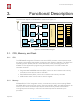
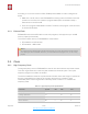

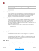
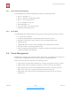
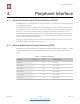
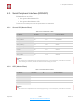

Table Of Contents
- Overview
- Wi-Fi Key Features
- Specifications
- Applications
- CPU, Memory, and Flash
- Clock
- Radio
- Wi-Fi
- Power Management
- General Purpose Input/Output Interface (GPIO)
- Secure Digital Input/Output Interface (SDIO)
- Serial Peripheral Interface (SPI/HSPI)
- I2C Interface
- I2S Interface
- Universal Asynchronous Receiver Transmitter (UART)
- Pulse-Width Modulation (PWM)
- IR Remote Control
- ADC (Analog-to-Digital Converter)
- Electrical Characteristics
- RF Power Consumption
- Wi-Fi Radio Characteristics
- Must-Read Documents
- Must-Have Resources

$
4. Peripheral Interface
4. Peripheral Interface
4.1. General Purpose Input/Output Interface (GPIO)
ESP8266EX has 17 GPIO pins which can be assigned to various functions by programming
the appropriate registers.
Each GPIO PAD can be configured with internal pull-up or pull-down (XPD_DCDC can only
be configured with internal pull-down, other GPIO PAD can only be configured with internal
pull-up), or set to high impedance. When configured as an input, the data are stored in
software registers; the input can also be set to edge-trigger or level trigger CPU interrupts.
In short, the IO pads are bi-directional, non-inverting and tristate, which includes input and
output buffer with tristate control inputs.
These pins, when working as GPIOs, can be multiplexed with other functions such as I2C,
I2S, UART, PWM, and IR Remote Control, etc.
4.2. Secure Digital Input/Output Interface (SDIO)
ESP8266EX has one Slave SDIO, the definitions of which are described as Table 4-1, which
supports 25 MHz SDIO v1.1 and 50 MHz SDIO v2.0, and 1 bit/4 bit SD mode and SPI
mode.
Table 4-1. Pin Definitions of SDIOs
Pin Name
Pin Num
IO
Function Name
SDIO_CLK
21
IO6
SDIO_CLK
SDIO_DATA0
22
IO7
SDIO_DATA0
SDIO_DATA1
23
IO8
SDIO_DATA1
SDIO_DATA_2
18
IO9
SDIO_DATA_2
SDIO_DATA_3
19
IO10
SDIO_DATA_3
SDIO_CMD
20
IO11
SDIO_CMD
Espressif
$ /$ 13 26
Submit Documentation Feedback
2020.10