
User's Manual


2. Hardware Preparation
2.1. Hardware Preparation
• ESP32-WATG-32D module
•
Espressif RF testing board (Carrier Board)
• One USB-to-UART dongle
• PC, Windows 7 recommended
• Micro-USB cable
2.2. Hardware Connection
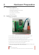
1. Solder ESP32-WATG-32D to the Carrier Board, as Figure 2 shows.
Figure 2: Testing Environment Setup(Needs Update)
2. Connect USB-to-UART dongle to the carrier board via TXD, RXD and GND.
3. Connect USB-to-UART dongle to the PC via the Micro-USB cable.
4. Connect the carrier board to 24 V adapter for power supply.
5. During download, short IO0 to GND via a jumper. Then, turn "ON" the board.
6. Download firmware into flash using the ESP32 DOWNLOAD TOOL.
7. After download, remove the jumper on IO0 and GND.
8. Power up the carrier board again. ESP32-WATG-32D will switch to working mode.
The chip will read programs from flash upon initialization.
📖 Notes:
• IO0 is internally logic high.
• For more information on ESP32-WATG-32D, please refer to ESP32-WATG-32D Datasheet.