
Data Sheet


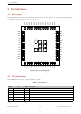
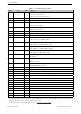
Table Of Contents
- 1 Module Overview
- 2 Block Diagram
- 3 Pin Definitions
- 4 Electrical Characteristics
- 8 Product Handling
- 9 MAC Addresses and eFuse
- 10 Learning Resources
- Revision History

3 Pin Definitions
3 Pin Definitions
3.1 Pin Layout
The pin diagram below shows the approximate location of pins on the module. For the actual diagram drawn to
scale, please refer to Section 7.1 Physical Dimensions.
Pin 55
GND
GNDGNDGND
GND
GNDGNDGND
GND
3V3
I37
I38
I39
EN
I34
I35
IO32
GND
I36
IO33
IO25
IO26
IO27
IO14
IO12
IO13
IO15
IO2
IO0
IO4
NC
NC
IO9
IO10
GND
IO23
NC
IO19
IO22
IO21
RXD0
TXD0
NC
GND
GND
GND
IO18
IO5
GND
GND
GND
GND
GND
GND
GND
GND
GND
GND
GND
GND
GND
GND
Pin 1
Pin 2
Pin 3
Pin 4
Pin 5
Pin 6
Pin 7
Pin 8
Pin 9
Pin 10
Pin 11
Pin 12
Pin 13
Pin 14
Pin 15
Pin 16
Pin 17
Pin 18
Pin 19
Pin 20
Pin 21
Pin 22
Pin 23
Pin 24
Pin 25
Pin 26
Pin 27
Pin 28
Pin 29
Pin 30
Pin 31
Pin 32
Pin 33
Pin 34
Pin 35
Pin 36
Pin 37
Pin 38
Pin 39
Pin 40
Pin 41
Pin 42
Pin 43
Pin 44
Pin 45
Pin 46
Pin 47
Pin 48
Pin 49
Pin 50
Pin 51
Pin 52
Pin 53
Pin 54
Figure 2: Pin Layout (Top View)
3.2 Pin Description
ESP32-MINI-1U has 55 pins. See pin definitions in Table 1.
Table 1: Pin Definitions
Name No. Type Function
GND 1, 2, 27, 38 ~ 55 P Ground
3V3 3 P Power supply
I36 4 I GPIO36, ADC1_CH0, RTC_GPIO0
I37 5 I GPIO37, ADC1_CH1, RTC_GPIO1
I38 6 I GPIO38, ADC1_CH2, RTC_GPIO2
I39 7 I GPIO39, ADC1_CH3, RTC_GPIO3
Cont’d on next page
Espressif Systems 10 ESP32-MINI-1U Datasheet v0.5