
Data Sheet
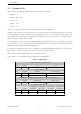
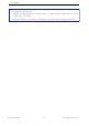
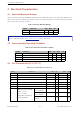
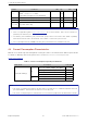
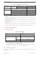
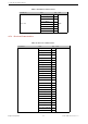
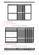
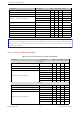
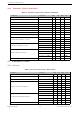
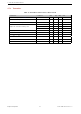
Table Of Contents
- 1 Module Overview
- 2 Block Diagram
- 3 Pin Definitions
- 4 Electrical Characteristics
- 8 Product Handling
- 9 MAC Addresses and eFuse
- 10 Learning Resources
- Revision History

4 Electrical Characteristics
Parameter Conditions Min Typ Max Unit
Gain control step - - 3 - dB
RF power control range - –12 - +9 dBm
+20 dB bandwidth - - 0.9 - MHz
Adjacent channel transmit power
F = F0 ± 2 MHz - –55 - dBm
F = F0 ± 3 MHz - –55 - dBm
F = F0 ± > 3 MHz - –59 - dBm
∆ f1
avg
- - - 155 kHz
∆ f2
max
- 127 - - kHz
∆ f2
avg
/∆ f1
avg
- - 0.92 - -
ICFT - - –7 - kHz
Drift rate - - 0.7 - kHz/50 µs
Drift (DH1) - - 6 - kHz
Drift (DH5) - - 6 - kHz
Note:
There are a total of eight power levels from 0 to 7, and the transmit power ranges from –12 dBm to 9 dBm. When the
power level rises by 1, the transmit power increases by 3 dB. Power level 4 is used by default and the corresponding
transmit power is 0 dBm.
4.6.3 Receiver –Enhanced Data Rate
Table 13: Receiver Characteristics –Enhanced Data Rate
Parameter Conditions Min Typ Max Unit
π/4 DQPSK
Sensitivity @0.01% BER - –90 –89 –88 dBm
Maximum received signal @0.01% BER - - 0 - dBm
Co-channel C/I - - 11 - dB
Adjacent channel selectivity C/I
F = F0 + 1 MHz - –7 - dB
F = F0 –1 MHz - –7 - dB
F = F0 + 2 MHz - –25 - dB
F = F0 –2 MHz - –35 - dB
F = F0 + 3 MHz - –25 - dB
F = F0 –3 MHz - –45 - dB
8DPSK
Sensitivity @0.01% BER - –84 –83 –82 dBm
Maximum received signal @0.01% BER - - –5 - dBm
C/I c-channel - - 18 - dB
Adjacent channel selectivity C/I
F = F0 + 1 MHz - 2 - dB
F = F0 –1 MHz - 2 - dB
F = F0 + 2 MHz - –25 - dB
F = F0 –2 MHz - –25 - dB
F = F0 + 3 MHz - –25 - dB
F = F0 –3 MHz - –38 - dB
Espressif Systems 19 ESP32-MINI-1U Datasheet v0.5