
Data Sheet
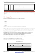
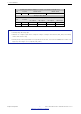
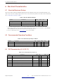
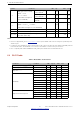
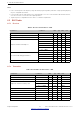
Table Of Contents

3 Pin Definitions
Enabling/Disabling Debugging Log Print over U0TXD During Booting
Pin Default U0TXD Active U0TXD Silent
MTDO Pull-up 1 0
Timing of SDIO Slave
Pin Default
FE Sampling
FE Output
FE Sampling
RE Output
RE Sampling
FE Output
RE Sampling
RE Output
MTDO Pull-up 0 0 1 1
GPIO5 Pull-up 0 1 0 1
Note:
• FE: falling-edge, RE: rising-edge.
• Firmware can configure register bits to change the settings of ”Voltage of Internal LDO (VDD_SDIO)” and ”Timing
of SDIO Slave” after booting.
• Internal pull-up resistor (R9) for MTDI is not populated in the module, as the flash and SRAM in the module only
support a power voltage of 3.3 V (output by VDD_SDIO).
Espressif Systems 7
Submit Documentation Feedback
ESP32-WROVER-E & ESP32-WROVER-IE Datasheet V1.4