
Data Sheet
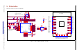
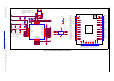
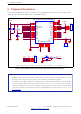
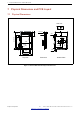
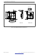
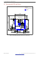
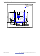
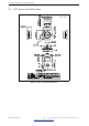
Table Of Contents
- 1 Module Overview
- 2 Block Diagram
- 3 Pin Definitions
- 4 Electrical Characteristics
- 5 Schematics
- 6 Peripheral Schematics
- 7 Physical Dimensions and PCB Layout
- 8 Product Handling
- 9 MAC Addresses and eFuse
- 10 Learning Resources
- Revision History

5 Schematics
5 Schematics
This is the reference design of the module.
5
5
4
4
3
3
2
2
1
1
D D
C C
B B
A A
EPAD
PCB ANTENNA
Pin.14
IO12
Pin.1
GND
Pin.2
3V3
Pin.3
EN
Pin.6
IO34
Pin.5
SENSOR_VN
Pin.4
SENSOR_VP
Pin.7
IO35
Pin.8
IO32
Pin.9
IO33
Pin.10
IO25
Pin.11
IO26
Pin.12
IO27
Pin.13
IO14
Pin.15
GND
Pin.16
IO13
Pin.17
NC
Pin.18
NC
Pin.19
NC
Pin.23
IO15
Pin.20
NC
Pin.21
NC
Pin.22
NC
Pin.24
IO2
Pin.37
IO23
Pin.36
IO22
Pin.28
IO17
Pin.32
NC
Pin.27
IO16
Pin.25
IO0
Pin.35
TXD0
Pin.30
IO18
Pin.26
IO4
Pin.34
RXD0
Pin.29
IO5
Pin.33
IO21
Pin.31
IO19
Pin.38
GND
The values of C1 and C2 vary with
the selection of the crystal.
The value of R2 varies with the actual
PCB board.
NC: No component.
The values of C15, L4 and C14
vary with the actual PCB board.
SENSOR_VP
SENSOR_VN
GPIO32
GPIO33
CHIP_PU
GPIO35
SCK/CLK
SCS/CMD
SENSOR_VP
SHD/SD2 SWP/SD3
SDI/SD1
SDO/SD0
SENSOR_VN
GPIO34
GPIO2
CHIP_PU
GPIO34
GPIO35
GPIO25
GPIO26
GPIO27
GPIO14
GPIO12
GPIO13
GPIO15
GPIO32
U0TXD
GPIO33
GPIO25
GPIO26
GPIO27
GPIO14
GPIO12
GPIO15
GPIO13
GPIO2
GPIO0
GPIO4
GPIO16
GPIO17
SDO/SD0
SDI/SD1
SCK/CLK
SWP/SD3
SCS/CMD
SHD/SD2
GPIO18
GPIO5
GPIO23
GPIO19
GPIO22
U0RXD
GPIO21
GPIO23
GPIO22
U0TXD
U0RXD
GPIO21
GPIO19
GPIO18
GPIO5
GPIO17
GPIO16
GPIO4
GPIO0
GND
GND
GND
VDD_SDIO
GND
GNDGND
GNDGND
GND
GND
GND
VDD33
GND
GNDGND
GND
GND
GND
GND GND
VDD33
GND
VDD33
GND
GND
GNDGND
VDD33
VDD33
VDD33
GND
VDD_SDIO
VDD33
Title
Size
Document Number Re v
Date: Sheet o f
<02_ESP32-WROOM-32E> V1.2
<ESP32-WROOM-32E>
C
2 2Tuesday, March 17, 2020
Title
Size
Document Number Re v
Date: Sheet o f
<02_ESP32-WROOM-32E> V1.2
<ESP32-WROOM-32E>
C
2 2Tuesday, March 17, 2020
Title
Size
Document Number Re v
Date: Sheet o f
<02_ESP32-WROOM-32E> V1.2
<ESP32-WROOM-32E>
C
2 2Tuesday, March 17, 2020
C18
1uF
R1 20K(5%)
C5
10nF/6.3V(10%)
C12
NC
C10
0.1uF
C19
0.1uF
C20
1uF
C3
100pF
L5 2.0nH
C2
TBD
C14
TBD
R2 0
L4 TBD
C17
NC
C6
3.3nF/6.3V(10%)
C9
0.1uF
C16
NC
C4
0.1uF
ANT1
PCB_ANT
1
2
C21
NC
C15
TBD
D1
LESD8D3.3CAT5G
U1
40MHz(±10ppm)
XIN
1
GND
2
XOUT
3
GND
4
R3 499
C11
1uF
C13
10uF
U2
ESP32-D0WD-V3
VDDA
1
LNA_IN
2
VDD3P3
3
VDD3P3
4
SENSOR_VP
5
SENSOR_CAPP
6
SENSOR_CAPN
7
SENSOR_VN
8
CHIP_PU
9
VDET_1
10
VDET_2
11
32K_XP
12
32K_XN
13
GPIO25
14
GPIO26
15
GPIO27
16
MTMS
17
MTDI
18
VDD3P3_RTC
19
MTCK
20
MTDO
21
GPIO2
22
GPIO0
23
GPIO4
24
VDD_SDIO
26
GPIO16
25
GPIO17
27
SD_DATA_2
28
SD_DATA_3
29
SD_CMD
30
SD_CLK
31
SD_DATA_0
32
GND
49
SD_DATA_1
33
GPIO5
34
GPIO18
35
GPIO19
38
CAP2
47
VDDA
43
XTAL_N
44
XTAL_P
45
GPIO23
36
U0TXD
41
GPIO22
39
GPIO21
42
VDD3P3_CPU
37
CAP1
48
VDDA
46
U0RXD
40
C1
TBD
U3
FLASH
/CS
1
DO
2
/WP
3
GND
4
DI
5
CLK
6
/HOLD
7
VCC
8
Figure 4: ESP32WROOM32E Schematics
Espressif Systems 22
Submit Documentation Feedback
ESP32-WROOM-32E & ESP32-WROOM-32UE Datasheet v1.2