
Data Sheet
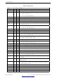
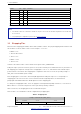
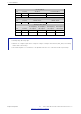
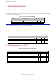
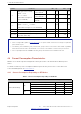
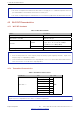
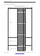

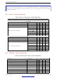
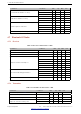
Table Of Contents
- 1 Module Overview
- 2 Block Diagram
- 3 Pin Definitions
- 4 Electrical Characteristics
- 5 Schematics
- 6 Peripheral Schematics
- 7 Physical Dimensions and PCB Layout
- 8 Product Handling
- 9 MAC Addresses and eFuse
- 10 Learning Resources
- Revision History

4 Electrical Characteristics
Parameter Rate Typ Unit
11n, HT40, MCS0 16
11n, HT40, MCS7 7
4.6 Bluetooth Radio
4.6.1 Receiver – Basic Data Rate
Table 11: Receiver Characteristics – Basic Data Rate
Parameter Conditions Min Typ Max Unit
Sensitivity @0.1% BER - –90 –89 –88 dBm
Maximum received signal @0.1% BER - 0 - - dBm
Co-channel C/I - - +7 - dB
Adjacent channel selectivity C/I
F = F0 + 1 MHz - - –6 dB
F = F0 – 1 MHz - - –6 dB
F = F0 + 2 MHz - - –25 dB
F = F0 – 2 MHz - - –33 dB
F = F0 + 3 MHz - - –25 dB
F = F0 – 3 MHz - - –45 dB
Out-of-band blocking performance
30 MHz ~ 2000 MHz –10 - - dBm
2000 MHz ~ 2400 MHz –27 - - dBm
2500 MHz ~ 3000 MHz –27 - - dBm
3000 MHz ~ 12.5 GHz –10 - - dBm
Intermodulation - –36 - - dBm
4.6.2 Transmitter – Basic Data Rate
Table 12: Transmitter Characteristics – Basic Data Rate
Parameter Conditions Min Typ Max Unit
RF transmit power (see note under Table 12) - - 0 - dBm
Gain control step - - 3 - dB
RF power control range - –12 - +9 dBm
+20 dB bandwidth - - 0.9 - MHz
Adjacent channel transmit power
F = F0 ± 2 MHz - –55 - dBm
F = F0 ± 3 MHz - –55 - dBm
F = F0 ± > 3 MHz - –59 - dBm
∆ f1
avg
- - - 155 kHz
∆ f2
max
- 127 - - kHz
∆ f2
avg
/∆ f1
avg
- - 0.92 - -
ICFT - - –7 - kHz
Drift rate - - 0.7 - kHz/50 µs
Drift (DH1) - - 6 - kHz
Drift (DH5) - - 6 - kHz
Espressif Systems 18
Submit Documentation Feedback
ESP32-WROOM-32E & ESP32-WROOM-32UE Datasheet v1.2