
Data Sheet
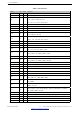
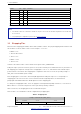
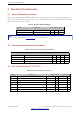
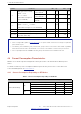
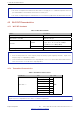

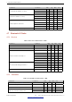
Table Of Contents
- 1 Module Overview
- 2 Block Diagram
- 3 Pin Definitions
- 4 Electrical Characteristics
- 5 Schematics
- 6 Peripheral Schematics
- 7 Physical Dimensions and PCB Layout
- 8 Product Handling
- 9 MAC Addresses and eFuse
- 10 Learning Resources
- Revision History

3 Pin Definitions
Booting Mode
Pin Default SPI Boot Download Boot
GPIO0 Pull-up 1 0
GPIO2 Pull-down Don’t-care 0
Enabling/Disabling Debugging Log Print over U0TXD During Booting
Pin Default U0TXD Active U0TXD Silent
MTDO Pull-up 1 0
Timing of SDIO Slave
Pin Default
FE Sampling
FE Output
FE Sampling
RE Output
RE Sampling
FE Output
RE Sampling
RE Output
MTDO Pull-up 0 0 1 1
GPIO5 Pull-up 0 1 0 1
Note:
• FE: falling-edge, RE: rising-edge.
• Firmware can configure register bits to change the settings of ”Voltage of Internal LDO (VDD_SDIO)” and ”Timing
of SDIO Slave”, after booting.
• The module integrates a 3.3 V SPI flash, so the pin MTDI cannot be set to 1 when the module is powered up.
Espressif Systems 13
Submit Documentation Feedback
ESP32-WROOM-32E & ESP32-WROOM-32UE Datasheet v1.2