
Data Sheet

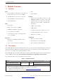
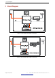
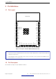
Table Of Contents
- 1 Module Overview
- 2 Block Diagram
- 3 Pin Definitions
- 4 Electrical Characteristics
- 5 Schematics
- 6 Peripheral Schematics
- 7 Physical Dimensions and PCB Layout
- 8 Product Handling
- 9 MAC Addresses and eFuse
- 10 Learning Resources
- Revision History

3 Pin Definitions
3 Pin Definitions
3.1 Pin Layout
1
2
3
4
5
6
7
8
9
10
11
12
13
14
GND
3V3
EN
SENSOR_VP
SENSOR_VN
IO34
IO35
IO32
IO33
IO25
IO26
IO27
IO14
IO12
15
16
17
18
19
20
21
22
23
24
GND
IO13
NC
NC
NC
NC
NC
NC
IO15
IO2
38
37
36
35
34
33
32
31
30
29
28
27
26
25
GND
IO23
IO22
TXD0
RXD0
IO21
NC
IO19
IO18
IO5
IO17
IO16
IO4
IO0
Pin 39
GND
Keepout Zone
GND
GND GND GND
GND
GNDGNDGND
Figure 3: Pin Layout of ESP32WROOM32E (Top View)
Note:
• The pin layout of ESP32-WROOM-32UE is the same as that of ESP32-WROOM-32E, except that ESP32-WROOM-
32UE has no keepout zone.
• The pin diagram shows the approximate location of pins on the module. For the actual mechanical diagram, please
refer to Section 7.1 Physical Dimensions.
3.2 Pin Description
The module has 38 pins. See pin definitions in Table 2.
Espressif Systems 10
Submit Documentation Feedback
ESP32-WROOM-32E & ESP32-WROOM-32UE Datasheet v1.2