
Data Sheet


2. Pin Definitions
2. Pin Definitions
2.1 Pin Layout
Keepout Zone
GND
IO23
IO22
TXD0
RXD0
IO21
NC
IO19
IO18
IO5
IO17
IO16
IO4
IO0
38
37
36
35
34
33
32
31
30
29
28
27
26
25
24
23
22
21
20
19
18
17
16
15
IO2
IO15
SD1
SD0
CLK
CMD
SD3
SD2
IO13
GND
1
2
3
4
5
6
7
8
9
10
11
12
13
14
GND
3V3
EN
SENSOR_VP
SENSOR_VN
IO34
IO35
IO32
IO33
IO25
IO26
IO27
IO14
IO12
39 GND
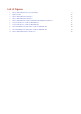
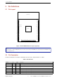
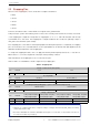
Figure 1: ESP32-WROOM-32D Pin Layout (Top View)
Note:
The pin layout of ESP32-WROOM-32U is the same as that of ESP32-WROOM-32D, except that ESP32-WROOM-32U
has no keepout zone.
2.2 Pin Description
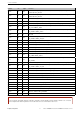
The ESP32-WROOM-32D and ESP32-WROOM-32U have 38 pins. See pin definitions in Table 3.
Table 3: Pin Definitions
Name No. Type Function
GND 1 P Ground
3V3 2 P Power supply
EN 3 I Module-enable signal. Active high.
SENSOR_VP 4 I GPIO36, ADC1_CH0, RTC_GPIO0
SENSOR_VN 5 I GPIO39, ADC1_CH3, RTC_GPIO3
IO34 6 I GPIO34, ADC1_CH6, RTC_GPIO4
IO35 7 I GPIO35, ADC1_CH7, RTC_GPIO5
Espressif Systems 3 ESP32-WROOM-32D & ESP32-WROOM-32U Datasheet V1.8