
Data Sheet
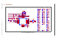
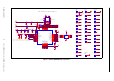
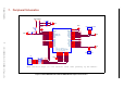

7. Peripheral Schematics
Note:
• Soldering Pad 39 to the Ground is not necessary for a satisfactory thermal performance. If users do want to solder it, they need to ensure that the correct quantity of soldering
paste is applied.
• When ESP32 is powered on and off repeatedly by switching the power rails, and there is a large capacitor on the 3V3 rail, a discharge circuit can be added to the 3V3 rail to ensure
proper power-on-reset. Please find the discharge circuit in Chapter Peripheral Schematics, in ESP32-WROOM-32 Datasheet.
• When battery is used as the power supply for ESP32 series of chips and modules, a supply voltage supervisor is recommended to avoid boot failure due to low voltage. Users are rec-
ommended to pull CHIP_PU low if the power supply for ESP32 is below 2.3 V. For the reset circuit, please refer to Chapter Peripheral Schematics, in ESP32-WROOM-32 Datasheet.
Espressif Systems 16 ESP32-WROOM-32D & ESP32-WROOM-32U Datasheet V1.8