ESP32-WROOM-32D & ESP32-WROOM-32U Datasheet Version 1.8 Espressif Systems Copyright © 2019 www.espressif.
About This Document This document provides the specifications for the ESP32-WROOM-32D and ESP32-WROOM-32U modules. Revision History For revision history of this document, please refer to the last page. Documentation Change Notification Espressif provides email notifications to keep customers updated on changes to technical documentation. Please subscribe at www.espressif.com/en/subscribe. Certification Download certificates for Espressif products from www.espressif.com/en/certificates.
Contents 1 Overview 1 2 Pin Definitions 3 2.1 Pin Layout 3 2.2 Pin Description 3 2.3 Strapping Pins 5 3 Functional Description 6 3.1 CPU and Internal Memory 6 3.2 External Flash and SRAM 6 3.3 Crystal Oscillators 6 3.4 RTC and Low-Power Management 7 4 Peripherals and Sensors 8 5 Electrical Characteristics 9 5.1 Absolute Maximum Ratings 9 5.2 Recommended Operating Conditions 9 5.3 DC Characteristics (3.3 V, 25 °C) 9 5.4 Wi-Fi Radio 10 5.5 BLE Radio 11 5.6 5.5.
List of Tables 1 ESP32-WROOM-32D vs. ESP32-WROOM-32U 1 2 ESP32-WROOM-32D and ESP32-WROOM-32U Specifications 2 3 Pin Definitions 3 4 Strapping Pins 5 5 Absolute Maximum Ratings 9 6 Recommended Operating Conditions 9 7 DC Characteristics (3.
List of Figures 1 ESP32-WROOM-32D Pin Layout (Top View) 3 2 Reflow Profile 12 3 ESP32-WROOM-32D Schematics 13 4 ESP32-WROOM-32U Schematics 14 5 ESP32-WROOM-32D & ESP32-WROOM-32U Peripheral Schematics 15 6 Physical Dimensions of ESP32-WROOM-32D 17 7 Physical Dimensions of ESP32-WROOM-32U 18 8 Recommended PCB Land Pattern of ESP32-WROOM-32D 19 9 Recommended PCB Land Pattern of ESP32-WROOM-32U 19 10 ESP32-WROOM-32U U.
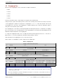
1. Overview 1. Overview ESP32-WROOM-32D and ESP32-WROOM-32U are powerful, generic Wi-Fi+BT+BLE MCU modules that target a wide variety of applications, ranging from low-power sensor networks to the most demanding tasks, such as voice encoding, music streaming and MP3 decoding. ESP32-WROOM-32U is different from ESP32-WROOM-32D in that ESP32-WROOM-32U integrates a U.FL connector. For detailed information of the U.FL connector please see Chapter 10.
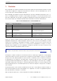
1. Overview Table 2: ESP32-WROOM-32D and ESP32-WROOM-32U Specifications Categories Certification Test Items Specifications RF Certification FCC/CE-RED/IC/TELEC/KCC/SRRC/NCC Wi-Fi Certification Wi-Fi Alliance Bluetooth certification BQB Green Certification REACH/RoHS Reliablity HTOL/HTSL/uHAST/TCT/ESD 802.11 b/g/n (802.11n up to 150 Mbps) Protocols Wi-Fi A-MPDU and A-MSDU aggregation and 0.4 µs guard interval support Frequency range 2.4 GHz ~ 2.5 GHz Protocols Bluetooth v4.
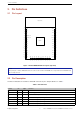
2. Pin Definitions 2. Pin Definitions 2.
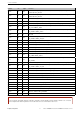
2. Pin Definitions Name No.
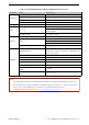
2. Pin Definitions 2.3 Strapping Pins ESP32 has five strapping pins, which can be seen in Chapter 6 Schematics: • MTDI • GPIO0 • GPIO2 • MTDO • GPIO5 Software can read the values of these five bits from register ”GPIO_STRAPPING”. During the chip’s system reset release (power-on-reset, RTC watchdog reset and brownout reset), the latches of the strapping pins sample the voltage level as strapping bits of ”0” or ”1”, and hold these bits until the chip is powered down or shut down.
3. Functional Description 3. Functional Description This chapter describes the modules and functions integrated in ESP32-WROOM-32D and ESP32-WROOM32U. 3.1 CPU and Internal Memory ESP32-D0WD contains a dual-core Xtensa® 32-bit LX6 MCU. The internal memory includes: • 448 KB of ROM for booting and core functions. • 520 KB of on-chip SRAM for data and instructions.
3. Functional Description 3.4 RTC and Low-Power Management With the use of advanced power-management technologies, ESP32 can switch between different power modes. For details on ESP32’s power consumption in different power modes, please refer to section ”RTC and Low-Power Management” in ESP32 Datasheet. Espressif Systems 7 ESP32-WROOM-32D & ESP32-WROOM-32U Datasheet V1.
4. Peripherals and Sensors 4. Peripherals and Sensors Please refer to Section Peripherals and Sensors in ESP32 Datasheet. Note: External connections can be made to any GPIO except for GPIOs in the range 6-11. These six GPIOs are connected to the module’s integrated SPI flash. For details, please see Section 6 Schematics. Espressif Systems 8 ESP32-WROOM-32D & ESP32-WROOM-32U Datasheet V1.
5. Electrical Characteristics 5. Electrical Characteristics 5.1 Absolute Maximum Ratings Stresses beyond the absolute maximum ratings listed in Table 5 below may cause permanent damage to the device. These are stress ratings only, and do not refer to the functional operation of the device that should follow the recommended operating conditions. Table 5: Absolute Maximum Ratings Symbol Parameter Min Max Unit VDD33 Power supply voltage –0.3 3.
5. Electrical Characteristics Symbol Parameter Min Typ Max Unit - 28 - mA Low-level sink current IOL (VDD1 = 3.3 V, VOL = 0.495 V, output drive strength set to the maximum) RP U Resistance of internal pull-up resistor - 45 - kΩ RP D Resistance of internal pull-down resistor - 45 - kΩ VIL_nRST Low-level input voltage of CHIP_PU to power off the chip - - 0.6 V Notes: 1. Please see Appendix IO_MUX of ESP32 Datasheet for IO’s power domain.
5. Electrical Characteristics 5.5 BLE Radio 5.5.1 Receiver Table 9: Receiver Characteristics – BLE Parameter Conditions Min Typ Max Unit Sensitivity @30.8% PER - - –97 - dBm Maximum received signal @30.
5. Electrical Characteristics Temperature (℃) 5.6 Reflow Profile Peak Temp. 235 ~ 250℃ 250 Preheating zone 150 ~ 200℃ 60 ~ 120s 217 200 Reflow zone !217℃ 60 ~ 90s Cooling zone -1 ~ -5℃/s Soldering time > 30s Ramp-up zone 1 ~ 3℃/s 100 50 25 Time (sec.) 0 0 50 100 150 200 250 Ramp-up zone — Temp.: <150℃ Time: 60 ~ 90s Ramp-up rate: 1 ~ 3℃/s Preheating zone — Temp.: 150 ~ 200℃ Time: 60 ~ 120s Ramp-up rate: 0.3 ~ 0.8℃/s Reflow zone — Temp.: >217℃ 7LPH 60 ~ 90s; Peak Temp.
6. Schematics Espressif Systems D 6. Schematics Pin.1 GND The values of C1 and C2 vary with the selection of the crystal. Pin.15 GND Pin.2 3V3 D1 LESD8D3.3CAT5G C1 22pF/6.3V(10%) 1 VDD33 C3 100pF GND 20K(5%) 3 C6 GND GND The values of C14 、 L4 and C15 vary with the actual PCB board. C16 NC C17 NC R2 48 47 46 45 44 43 42 41 40 39 CAP1 CAP2 VDDA XTAL_P XTAL_N VDDA GPIO21 U0TXD U0RXD GPIO22 GND VDD33 C4 0.
D Pin.2 3V3 1 C5 10nF/6.3V(10%) C6 GND GND GND U0TXD Pin.34 U0RXD SCS/CMD Pin.20 CLK U0RXD Pin.33 IO21 SCK/CLK GPIO21 3 CAP1 CAP2 VDDA XTAL_P XTAL_N VDDA GPIO21 U0TXD U0RXD GPIO22 VDD33 C4 0.1uF Pin.7 IO35 VDD_SDIO Pin.21 SD0 GPIO35 Pin.32 NC SDO/SD0 GND C16 NC C17 NC 14 The values of C14 、 L4 and C15 vary with the actual PCB board.
7. Peripheral Schematics Espressif Systems 7. Peripheral Schematics VDD33 VDD33 C1 10uF C2 0.1uF GND GND GND 0.1uF EN C3 15 16 17 18 19 20 21 22 23 24 U2 MTMS MTDI MTCK MTDO 39 38 37 36 35 34 33 32 31 30 29 28 27 26 25 J1 IO23 IO22 TXD RXD IO21 GND IO19 IO18 IO5 IO17 IO16 IO4 IO0 GND J2 BOOT OPTION GND 1 2 3 4 R2 R3 R4 R5 100R 100R 100R 100R MTMS MTDI MTCK MTDO IO2 ESP32-WROOM-32D & ESP32-WROOM-32U Datasheet V1.
• Soldering Pad 39 to the Ground is not necessary for a satisfactory thermal performance. If users do want to solder it, they need to ensure that the correct quantity of soldering paste is applied. • When ESP32 is powered on and off repeatedly by switching the power rails, and there is a large capacitor on the 3V3 rail, a discharge circuit can be added to the 3V3 rail to ensure proper power-on-reset. Please find the discharge circuit in Chapter Peripheral Schematics, in ESP32-WROOM-32 Datasheet.
ESP32-WROOM-32D DIMENSIONS Unit: mm Module Width 18.00±0.10 3.10±0.10 18.00±0.10 Module Thickness 6.20±0.10 0.80±0.10 Antenna Area 0.45±0.10 0.85±0.10 PCB Thickness 0.90±0.10 0.90±0.10 3.60±0.10 17 25.50±0.10 25.50±0.10 17.60±0.10 5.70±0.10 ESP32-WROOM-32D & ESP32-WROOM-32U Datasheet V1.8 8.50±0.10 ∅0.50±0.10 1.27±0.10 1.50±0.10 3.60±0.10 16.51±0.10 Module Length 1.27±0.10 15.80±0.10 1.50±0.10 1.27±0.10 3.28±0.10 3.28±0.10 11.43±0.
8. Physical Dimensions Espressif Systems ESP32-WROOM-32U DIMENSIONS Unit: mm Module Width 3.20±0.10 18.00±0.10 Module Thickness 3.25±0.10 0.45±0.10 18.00±0.10 0.90±0.10 0.80±0.10 3.00±0.10 0.85±0.10 PCB Thickness 0.90±0.10 10.75±0.10 13.05±0.10 3.60±0.10 19.20±0.10 18 Module Length ESP32-WROOM-32D & ESP32-WROOM-32U Datasheet V1.8 1.27±0.10 1.50±0.10 16.51±0.10 17.50±0.10 3.60±0.10 19.20±0.10 5.70±0.10 15.65±0.10 8.50±0.10 1.27±0.10 1.27±0.10 11.43±0.10 1.50±0.10 3.28±0.10 3.
9. Recommended PCB Land Pattern 9. Recommended PCB Land Pattern Unit:mm 0.9 6.3 2 1 38 5 6.51 5 1.27x13=16.51 25.5 4 15 2.785 1 7.49 18 24 1.27x9=11.43 2.785 17 Figure 8: Recommended PCB Land Pattern of ESP32-WROOM-32D Unit:mm 18 2 1 38 5 15 2.785 1 6.51 5 1.27x13=16.51 19.2 0.9 4 24 1.27x9=11.43 2.785 17 Figure 9: Recommended PCB Land Pattern of ESP32-WROOM-32U Espressif Systems 19 ESP32-WROOM-32D & ESP32-WROOM-32U Datasheet V1.
10. U.FL Connector Dimensions 10. U.FL Connector Dimensions Unit: mm Figure 10: ESP32-WROOM-32U U.FL Dimensions Espressif Systems 20 ESP32-WROOM-32D & ESP32-WROOM-32U Datasheet V1.
11. Learning Resources 11. Learning Resources 11.1 Must-Read Documents The following link provides documents related to ESP32. • ESP32 Datasheet This document provides an introduction to the specifications of the ESP32 hardware, including overview, pin definitions, functional description, peripheral interface, electrical characteristics, etc. • ESP-IDF Programming Guide It hosts extensive documentation for ESP-IDF ranging from hardware guides to API reference.
Revision History Revision History Date Version Release notes 2019.01 V1.8 Changed the RF power control range in Table 10 from –12 ~ +12 to –12 ~ +9 dBm. Added notice on module custom options under Table 2; 2018.10 V1.7 Added ”Cumulative IO output current” entry to Table 5: Absolute Maximum Ratings; Added more parameters to Table 7: DC Characteristics. 2018.09 V1.6 Updated the hole diameter in the shield from 1.00 mm to 0.50 mm, in Figure 6.