
Datasheet


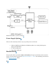

Connect the board with the computer using USB-to-UART Port. Connection using ESP32-S3
USB Port is not fully implemented in software. In subsequent steps, USB-to-UART Port will
be used by default.
Software Setup
Please proceed to Get Started, where Section Installation will quickly help you set up the
development environment and then flash an application example onto your board.
Contents and Packaging
Ordering Information
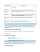
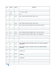
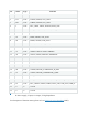
The development board has a variety of variants to choose from, as shown in the table below.
Ordering Code
Module Integrated
Flash
PSRAM
SPI Voltage
ESP32-S3-DevKitC-1-
N8
ESP32-S3-WROOM-1-N8
8 MB
QD
—
3.3 V
ESP32-S3-DevKitC-1-
N8R2
ESP32-S3-WROOM-1-
N8R2
8 MB
QD
2 MB
QD
3.3 V
ESP32-S3-DevKitC-1-
N8R8
ESP32-S3-WROOM-1-
N8R8
8 MB
QD
8 MB
OT
3.3 V
ESP32-S3-DevKitC-1-
N16R8V
ESP32-S3-WROOM-2-
N16R8V
16 MB
OT
8 MB
OT
1.8 V
ESP32-S3-DevKitC-1-
N32R8V
ESP32-S3-WROOM-2-
N32R8V
32 MB
OT
8 MB
OT
1.8 V
ESP32-S3-DevKitC-1U-
N8
ESP32-S3-WROOM-1U-
N8
8 MB
QD
—
3.3 V
ESP32-S3-DevKitC-1U-
N8R2
ESP32-S3-WROOM-1U-
N8R2
8 MB
QD
2 MB
QD
3.3 V
ESP32-S3-DevKitC-1U-
N8R8
ESP32-S3-WROOM-1U-
N8R8
8 MB
QD
8 MB
OT
3.3 V
Note
In the table above, QD stands for Quad SPI and OT stands for Octal SPI.