
Datasheet


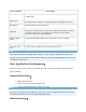
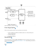
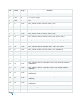

Key Component
Description
Port
to the chip, as well as for communication with the chip via the on-board USB-to-
UART bridge.
Boot Button
Download button. Holding down Boot and then pressing Reset initiates
Firmware Download mode for downloading firmware through the serial port.
Reset Button
Press this button to restart the system.
USB Port
ESP32-S3 full-speed USB OTG interface, compliant with the USB 1.1
specification. The interface is used for power supply to the board, for flashing
applications to the chip, for communication with the chip using USB 1.1
protocols, as well as for JTAG debugging.
USB-to-UART
Bridge
Single USB-to-UART bridge chip provides transfer rates up to 3 Mbps.
RGB LED
Addressable RGB LED, driven by GPIO38.
3.3 V Power On
LED
Turns on when the USB power is connected to the board.
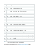
Note
For boards with ESP32-S3-WROOM-2 modules, the pins GPIO35, GPIO36 and GPIO37 are
used for the internal communication between ESP32-S3 and SPI flash/PSRAM memory, thus not
available for external use.
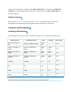
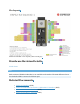
Start Application Development
Before powering up your board, please make sure that it is in good condition with no obvious
signs of damage.
Required Hardware
• ESP32-S3-DevKitC-1
• USB 2.0 cable (Standard-A to Micro-B)
• Computer running Windows, Linux, or macOS
Note
Be sure to use an appropriate USB cable. Some cables are for charging only and do not provide
the needed data lines nor work for programming the boards.
Hardware Setup