
Datasheet


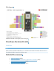

This section provides a brief introduction of ESP32-S3-DevKitC-1, instructions on how to do the
initial hardware setup and how to flash firmware onto it.
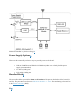
Description of Components
ESP32-S3-DevKitC-1 - front
The key components of the board are described in a counter-clockwise direction.
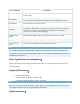
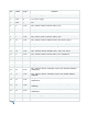
Key Component
Description
ESP32-S3-
WROOM-1/1U/2
ESP32-S3-WROOM-1, ESP32-S3-WROOM-1U, and ESP32-S3-WROOM-2 are
powerful, generic Wi-Fi + Bluetooth LE MCU modules that have a rich set of
peripherals. They provide acceleration for neural network computing and signal
processing workloads. ESP32-S3-WROOM-1 and ESP32-S3-WROOM-2 comes
with a PCB antenna. ESP32-S3-WROOM-1U comes with an external antenna
connector.
5 V to 3.3 V LDO
Power regulator that converts a 5 V supply into a 3.3 V output.
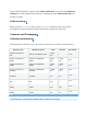
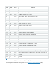
Pin Headers
All available GPIO pins (except for the SPI bus for flash) are broken out to the
pin headers on the board for easy interfacing and programming. For details,
please see Header Block.
USB-to-UART
A Micro-USB port used for power supply to the board, for flashing applications