
Data Sheet

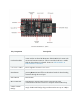

Key Component
Description
3.3 V Power On
LED
Turns on when the USB is connected to the board. For details, please
see the schematics in Related Documents.
I/O Connector
All available GPIO pins (except for the SPI bus for flash) are broken
out to the pin headers on the board. Users can program ESP32 chip
to enable multiple functions.
Start Application Development
Before powering up your ESP32-DevKitM-1, please make sure that it is in good
condition with no obvious signs of damage.
Required Hardware
• ESP32-DevKitM-1
• USB 2.0 cable (Standard-A to Micro-B)
• Computer running Windows, Linux, or macOS
Software Setup
Please proceed to Get Started, where Section Installation Step by Step will quickly help
you set up the development environment and then flash an application example onto
your ESP32-DevKitM-1.
Attention
ESP32-DevKitM-1 is a board with a single core module, please enable single core mode
(CONFIG_FREERTOS_UNICORE) in menuconfig before flashing your applications.
Hardware Reference
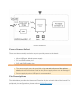
Block Diagram
A block diagram below shows the components of ESP32-DevKitM-1 and their
interconnections.