
Data Sheet
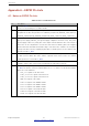
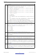
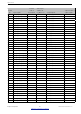
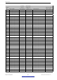
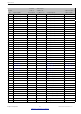
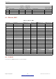
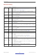
Table Of Contents
- 1 Overview
- 2 Pin Definitions
- 3 Functional Description
- 4 Peripherals and Sensors
- 4.1 Descriptions of Peripherals and Sensors
- 4.1.1 General Purpose Input / Output Interface (GPIO)
- 4.1.2 Analog-to-Digital Converter (ADC)
- 4.1.3 Hall Sensor
- 4.1.4 Digital-to-Analog Converter (DAC)
- 4.1.5 Touch Sensor
- 4.1.6 Ultra-Low-Power Co-processor
- 4.1.7 Ethernet MAC Interface
- 4.1.8 SD/SDIO/MMC Host Controller
- 4.1.9 SDIO/SPI Slave Controller
- 4.1.10 Universal Asynchronous Receiver Transmitter (UART)
- 4.1.11 I²C Interface
- 4.1.12 I²S Interface
- 4.1.13 Infrared Remote Controller
- 4.1.14 Pulse Counter
- 4.1.15 Pulse Width Modulation (PWM)
- 4.1.16 LED PWM
- 4.1.17 Serial Peripheral Interface (SPI)
- 4.1.18 Accelerator
- 4.2 Peripheral Pin Configurations
- 4.1 Descriptions of Peripherals and Sensors
- 5 Electrical Characteristics
- 6 Package Information
- 7 Part Number and Ordering Information
- 8 Learning Resources
- Appendix A – ESP32 Pin Lists
- Revision History

Appendix A
No. Description
7
Each column about digital “Function” is accompanied by a column about “Type”. Please see
the following explanations for the meanings of “type” with respect to each “function” they are
associated with. For each “Function-N”, “type” signifies:
• I: input only. If a function other than “Function-N” is assigned, the input signal of
“Function-N” is still from this pin.
• I1: input only. If a function other than “Function-N” is assigned, the input signal of
“Function-N” is always “1”.
• I0: input only. If a function other than “Function-N” is assigned, the input signal of
“Function-N” is always “0”.
• O: output only.
• T: high-impedance.
• I/O/T: combinations of input, output, and high-impedance according to the function sig-
nal.
• I1/O/T: combinations of input, output, and high-impedance, according to the function
signal. If a function is not selected, the input signal of the function is “1”.
For example, pin 30 can function as HS1_CMD or SD_CMD, where HS1_CMD is of an “I1/O/T”
type. If pin 30 is selected as HS1_CMD, this pin’s input and output are controlled by the SDIO
host. If pin 30 is not selected as HS1_CMD, the input signal of the SDIO host is always “1”.
8
Each digital output pin is associated with its configurable drive strength. Column “Drive
Strength” in Table IO_MUX lists the default values. The drive strength of the digital output
pins can be configured into one of the following four options:
• 0: ~5 mA
• 1: ~10 mA
• 2: ~20 mA
• 3: ~40 mA
The default value is 2.
The drive strength of the internal pull-up (wpu) and pull-down (wpd) is ~75 µA.
9
Column “At Reset” in Table IO_MUX lists the status of each pin during reset, including input-
enable (ie=1), internal pull-up (wpu) and internal pull-down (wpd). During reset, all pins are
output-disabled.
10
Column “After Reset” in Table IO_MUX lists the status of each pin immediately after reset,
including input-enable (ie=1), internal pull-up (wpu) and internal pull-down (wpd). After reset,
each pin is set to “Function 1”. The output-enable is controlled by digital Function 1.
11
Table Ethernet_MAC is about the signal mapping inside Ethernet MAC. The Ethernet MAC
supports MII and RMII interfaces, and supports both the internal PLL clock and the external
clock source. For the MII interface, the Ethernet MAC is with/without the TX_ERR signal. MDC,
MDIO, CRS and COL are slow signals, and can be mapped onto any GPIO pin through the
GPIO-Matrix.
12
Table GPIO Matrix is for the GPIO-Matrix. The signals of the on-chip functional modules can
be mapped onto any GPIO pin. Some signals can be mapped onto a pin by both IO-MUX
and GPIO-Matrix, as shown in the column tagged as “Same input signal from IO_MUX core”
in Table GPIO Matrix.
Espressif Systems 52
Submit Documentation Feedback
ESP32 Series Datasheet v3.5