
Data Sheet
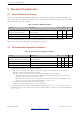
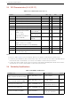
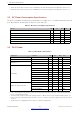
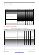
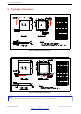
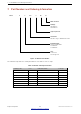
Table Of Contents
- 1 Overview
- 2 Pin Definitions
- 3 Functional Description
- 4 Peripherals and Sensors
- 4.1 Descriptions of Peripherals and Sensors
- 4.1.1 General Purpose Input / Output Interface (GPIO)
- 4.1.2 Analog-to-Digital Converter (ADC)
- 4.1.3 Hall Sensor
- 4.1.4 Digital-to-Analog Converter (DAC)
- 4.1.5 Touch Sensor
- 4.1.6 Ultra-Low-Power Co-processor
- 4.1.7 Ethernet MAC Interface
- 4.1.8 SD/SDIO/MMC Host Controller
- 4.1.9 SDIO/SPI Slave Controller
- 4.1.10 Universal Asynchronous Receiver Transmitter (UART)
- 4.1.11 I²C Interface
- 4.1.12 I²S Interface
- 4.1.13 Infrared Remote Controller
- 4.1.14 Pulse Counter
- 4.1.15 Pulse Width Modulation (PWM)
- 4.1.16 LED PWM
- 4.1.17 Serial Peripheral Interface (SPI)
- 4.1.18 Accelerator
- 4.2 Peripheral Pin Configurations
- 4.1 Descriptions of Peripherals and Sensors
- 5 Electrical Characteristics
- 6 Package Information
- 7 Part Number and Ordering Information
- 8 Learning Resources
- Appendix A – ESP32 Pin Lists
- Revision History

7 Part Number and Ordering Information
7 Part Number and Ordering Information
ESP32 - D WD Q6
Package
Q6=QFN 6*6
N/A=QFN 5*5
Connection
WD=Wi-Fi b/g/n + BT/BLE dual mode
Core
D=Dual core
S=Single core
0
Embedded flash
0=No embedded flash
2=2 MB flash
4=4 MB flash
V3
Wafer version 3
H
Figure 10: ESP32 Part Number
The table below provides the ordering information of the ESP32 series of chips.
Table 23: ESP32 Ordering Information
Ordering code Core Embedded flash Package
ESP32-D0WD-V3 Dual core No embedded flash QFN 5*5
ESP32-D0WDQ6-V3 Dual core No embedded flash QFN 6*6
ESP32-D0WD Dual core No embedded flash QFN 5*5
ESP32-D0WDQ6 Dual core No embedded flash QFN 6*6
ESP32-D2WD Dual core 2 MB embedded flash (40 MHz) QFN 5*5
ESP32-S0WD Single core No embedded flash QFN 5*5
ESP32-U4WDH Single core 4 MB embedded flash (80 MHz) QFN 5*5
Note: All above chips support Wi-Fi b/g/n + BT/BLE Dual Mode connection.
Espressif Systems 49
Submit Documentation Feedback
ESP32 Series Datasheet v3.5