
Data Sheet
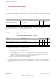
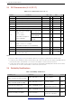
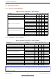
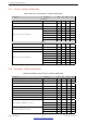
Table Of Contents
- 1 Overview
- 2 Pin Definitions
- 3 Functional Description
- 4 Peripherals and Sensors
- 4.1 Descriptions of Peripherals and Sensors
- 4.1.1 General Purpose Input / Output Interface (GPIO)
- 4.1.2 Analog-to-Digital Converter (ADC)
- 4.1.3 Hall Sensor
- 4.1.4 Digital-to-Analog Converter (DAC)
- 4.1.5 Touch Sensor
- 4.1.6 Ultra-Low-Power Co-processor
- 4.1.7 Ethernet MAC Interface
- 4.1.8 SD/SDIO/MMC Host Controller
- 4.1.9 SDIO/SPI Slave Controller
- 4.1.10 Universal Asynchronous Receiver Transmitter (UART)
- 4.1.11 I²C Interface
- 4.1.12 I²S Interface
- 4.1.13 Infrared Remote Controller
- 4.1.14 Pulse Counter
- 4.1.15 Pulse Width Modulation (PWM)
- 4.1.16 LED PWM
- 4.1.17 Serial Peripheral Interface (SPI)
- 4.1.18 Accelerator
- 4.2 Peripheral Pin Configurations
- 4.1 Descriptions of Peripherals and Sensors
- 5 Electrical Characteristics
- 6 Package Information
- 7 Part Number and Ordering Information
- 8 Learning Resources
- Appendix A – ESP32 Pin Lists
- Revision History

5 Electrical Characteristics
5.7 Bluetooth Radio
5.7.1 Receiver – Basic Data Rate
Table 17: Receiver Characteristics – Basic Data Rate
Parameter Conditions Min Typ Max Unit
Sensitivity @0.1% BER - –90 –89 –88 dBm
Maximum received signal @0.1% BER - 0 - - dBm
Co-channel C/I - - +7 - dB
Adjacent channel selectivity C/I
F = F0 + 1 MHz - - –6 dB
F = F0 – 1 MHz - - –6 dB
F = F0 + 2 MHz - - –25 dB
F = F0 – 2 MHz - - –33 dB
F = F0 + 3 MHz - - –25 dB
F = F0 – 3 MHz - - –45 dB
Out-of-band blocking performance
30 MHz ~ 2000 MHz –10 - - dBm
2000 MHz ~ 2400 MHz –27 - - dBm
2500 MHz ~ 3000 MHz –27 - - dBm
3000 MHz ~ 12.5 GHz –10 - - dBm
Intermodulation - –36 - - dBm
5.7.2 Transmitter – Basic Data Rate
Table 18: Transmitter Characteristics – Basic Data Rate
Parameter Conditions Min Typ Max Unit
RF transmit power (see note under Table 18) - - 0 - dBm
Gain control step - - 3 - dB
RF power control range - –12 - +9 dBm
+20 dB bandwidth - - 0.9 - MHz
Adjacent channel transmit power
F = F0 ± 2 MHz - –47 - dBm
F = F0 ± 3 MHz - –55 - dBm
F = F0 ± > 3 MHz - –60 - dBm
∆ f1
avg
- - - 155 kHz
∆ f2
max
- 133.7 - - kHz
∆ f2
avg
/∆ f1
avg
- - 0.92 - -
ICFT - - –7 - kHz
Drift rate - - 0.7 - kHz/50 µs
Drift (DH1) - - 6 - kHz
Drift (DH5) - - 6 - kHz
Note:
There are a total of eight power levels from 0 to 7, and the transmit power ranges from –12 dBm to 9 dBm. When the
power level rises by 1, the transmit power increases by 3 dB. Power level 4 is used by default and the corresponding
transmit power is 0 dBm.
Espressif Systems 45
Submit Documentation Feedback
ESP32 Series Datasheet v3.5