
Data Sheet
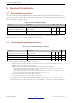
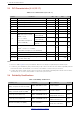
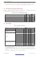
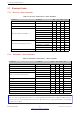
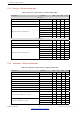
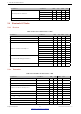
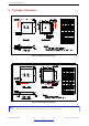
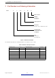
Table Of Contents
- 1 Overview
- 2 Pin Definitions
- 3 Functional Description
- 4 Peripherals and Sensors
- 4.1 Descriptions of Peripherals and Sensors
- 4.1.1 General Purpose Input / Output Interface (GPIO)
- 4.1.2 Analog-to-Digital Converter (ADC)
- 4.1.3 Hall Sensor
- 4.1.4 Digital-to-Analog Converter (DAC)
- 4.1.5 Touch Sensor
- 4.1.6 Ultra-Low-Power Co-processor
- 4.1.7 Ethernet MAC Interface
- 4.1.8 SD/SDIO/MMC Host Controller
- 4.1.9 SDIO/SPI Slave Controller
- 4.1.10 Universal Asynchronous Receiver Transmitter (UART)
- 4.1.11 I²C Interface
- 4.1.12 I²S Interface
- 4.1.13 Infrared Remote Controller
- 4.1.14 Pulse Counter
- 4.1.15 Pulse Width Modulation (PWM)
- 4.1.16 LED PWM
- 4.1.17 Serial Peripheral Interface (SPI)
- 4.1.18 Accelerator
- 4.2 Peripheral Pin Configurations
- 4.1 Descriptions of Peripherals and Sensors
- 5 Electrical Characteristics
- 6 Package Information
- 7 Part Number and Ordering Information
- 8 Learning Resources
- Appendix A – ESP32 Pin Lists
- Revision History

5 Electrical Characteristics
1. JEDEC document JEP157 states that 250 V CDM allows safe manufacturing with a standard ESD control process.
2. JEDEC document JEP155 states that 500 V HBM allows safe manufacturing with a standard ESD control process.
5.5 RF PowerConsumption Specifications
The power consumption measurements are taken with a 3.3 V supply at 25 °C of ambient temperature at the RF
port. All transmitters’ measurements are based on a 50% duty cycle.
Table 15: RF PowerConsumption Specifications
Mode Min Typ Max Unit
Transmit 802.11b, DSSS 1 Mbps, POUT = +19.5 dBm - 240 - mA
Transmit 802.11g, OFDM 54 Mbps, POUT = +16 dBm - 190 - mA
Transmit 802.11n, OFDM MCS7, POUT = +14 dBm - 180 - mA
Receive 802.11b/g/n - 95 ~ 100 - mA
Transmit BT/BLE, POUT = 0 dBm - 130 - mA
Receive BT/BLE - 95 ~ 100 - mA
5.6 WiFi Radio
Table 16: WiFi Radio Characteristics
Parameter Condition Min Typ Max Unit
Operating frequency range
note1
- 2412 - 2484 MHz
Output impedance
note2
- - note 2 - Ω
TX power
note3
11n, MCS7 12 13 14 dBm
11b mode 18.5 19.5 20.5 dBm
Sensitivity
11b, 1 Mbps - –98 - dBm
11b, 11 Mbps - –88 - dBm
11g, 6 Mbps - –93 - dBm
11g, 54 Mbps - –75 - dBm
11n, HT20, MCS0 - –93 - dBm
11n, HT20, MCS7 - –73 - dBm
11n, HT40, MCS0 - –90 - dBm
11n, HT40, MCS7 - –70 - dBm
Adjacent channel rejection
11g, 6 Mbps - 27 - dB
11g, 54 Mbps - 13 - dB
11n, HT20, MCS0 - 27 - dB
11n, HT20, MCS7 - 12 - dB
1. Device should operate in the frequency range allocated by regional regulatory authorities. Target operating frequency
range is configurable by software.
2. The typical value of ESP32’s Wi-Fi radio output impedance is different between chips in different QFN packages. For
ESP32 chips with a QFN 6×6 package, the value is 30+j10 Ω. For ESP32 chips with a QFN 5×5 package, the value is
35+j10 Ω.
3. Target TX power is configurable based on device or certification requirements.
Espressif Systems 44
Submit Documentation Feedback
ESP32 Series Datasheet v3.5