
Data Sheet
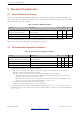
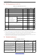
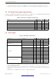
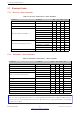
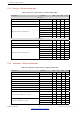
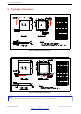
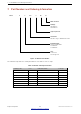
Table Of Contents
- 1 Overview
- 2 Pin Definitions
- 3 Functional Description
- 4 Peripherals and Sensors
- 4.1 Descriptions of Peripherals and Sensors
- 4.1.1 General Purpose Input / Output Interface (GPIO)
- 4.1.2 Analog-to-Digital Converter (ADC)
- 4.1.3 Hall Sensor
- 4.1.4 Digital-to-Analog Converter (DAC)
- 4.1.5 Touch Sensor
- 4.1.6 Ultra-Low-Power Co-processor
- 4.1.7 Ethernet MAC Interface
- 4.1.8 SD/SDIO/MMC Host Controller
- 4.1.9 SDIO/SPI Slave Controller
- 4.1.10 Universal Asynchronous Receiver Transmitter (UART)
- 4.1.11 I²C Interface
- 4.1.12 I²S Interface
- 4.1.13 Infrared Remote Controller
- 4.1.14 Pulse Counter
- 4.1.15 Pulse Width Modulation (PWM)
- 4.1.16 LED PWM
- 4.1.17 Serial Peripheral Interface (SPI)
- 4.1.18 Accelerator
- 4.2 Peripheral Pin Configurations
- 4.1 Descriptions of Peripherals and Sensors
- 5 Electrical Characteristics
- 6 Package Information
- 7 Part Number and Ordering Information
- 8 Learning Resources
- Appendix A – ESP32 Pin Lists
- Revision History

5 Electrical Characteristics
5 Electrical Characteristics
5.1 Absolute Maximum Ratings
Stresses beyond the absolute maximum ratings listed in the table below may cause permanent damage to the
device. These are stress ratings only, and do not refer to the functional operation of the device that should follow
the recommended operating conditions.
Table 11: Absolute Maximum Ratings
Symbol Parameter Min Max Unit
VDDA, VDD3P3, VDD3P3_RTC,
VDD3P3_CPU, VDD_SDIO
Voltage applied to power supply pins per
power domain
–0.3 3.6 V
I
output
* Cumulative IO output current - 1200 mA
T
store
Storage temperature –40 150 °C
* The chip worked properly after a 24-hour test in ambient temperature at 25 °C, and the IOs in three domains
(VDD3P3_RTC, VDD3P3_CPU, VDD_SDIO) output high logic level to ground.
5.2 Recommended Operating Conditions
Table 12: Recommended Operating Conditions
Symbol Parameter Min Typ Max Unit
VDDA, VDD3P3_RTC
1
VDD3P3, VDD_SDIO (3.3 V mode)
2
Voltage applied to power supply pins per
power domain
2.3 3.3 3.6 V
VDD3P3_CPU Voltage applied to power supply pin 1.8 3.3 3.6 V
I
V DD
Current delivered by external power supply 0.5 - - A
T
3
Operating temperature –40 - 125 °C
1. When writing eFuse, VDD3P3_RTC should be at least 3.3 V.
2. • VDD_SDIO works as the power supply for the related IO, and also for an external device. Please refer to the
Appendix IO_MUX of this datasheet for more details.
• VDD_SDIO can be sourced internally by the ESP32 from the VDD3P3_RTC power domain:
– When VDD_SDIO operates at 3.3 V, it is driven directly by VDD3P3_RTC through a 6 Ω resistor, therefore,
there will be some voltage drop from VDD3P3_RTC.
– When VDD_SDIO operates at 1.8 V, it can be generated from ESP32’s internal LDO. The maximum current
this LDO can offer is 40 mA, and the output voltage range is 1.65 V ~ 2.0 V.
• VDD_SDIO can also be driven by an external power supply.
• Please refer to Power Scheme, section 2.3, for more information.
3. The operating temperature of ESP32-D2WD and ESP32-U4WDH ranges from –40 °C to 105 °C, due to the flash
embedded in them. The other chips in this series have no embedded flash, so their range of operating temperatures is
–40 °C ~ 125 °C.
Espressif Systems 42
Submit Documentation Feedback
ESP32 Series Datasheet v3.5