
Data Sheet
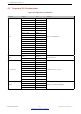
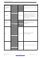

Table Of Contents
- 1 Overview
- 2 Pin Definitions
- 3 Functional Description
- 4 Peripherals and Sensors
- 4.1 Descriptions of Peripherals and Sensors
- 4.1.1 General Purpose Input / Output Interface (GPIO)
- 4.1.2 Analog-to-Digital Converter (ADC)
- 4.1.3 Hall Sensor
- 4.1.4 Digital-to-Analog Converter (DAC)
- 4.1.5 Touch Sensor
- 4.1.6 Ultra-Low-Power Co-processor
- 4.1.7 Ethernet MAC Interface
- 4.1.8 SD/SDIO/MMC Host Controller
- 4.1.9 SDIO/SPI Slave Controller
- 4.1.10 Universal Asynchronous Receiver Transmitter (UART)
- 4.1.11 I²C Interface
- 4.1.12 I²S Interface
- 4.1.13 Infrared Remote Controller
- 4.1.14 Pulse Counter
- 4.1.15 Pulse Width Modulation (PWM)
- 4.1.16 LED PWM
- 4.1.17 Serial Peripheral Interface (SPI)
- 4.1.18 Accelerator
- 4.2 Peripheral Pin Configurations
- 4.1 Descriptions of Peripherals and Sensors
- 5 Electrical Characteristics
- 6 Package Information
- 7 Part Number and Ordering Information
- 8 Learning Resources
- Appendix A – ESP32 Pin Lists
- Revision History

4 Peripherals and Sensors
4.1.15 Pulse Width Modulation (PWM)
The Pulse Width Modulation (PWM) controller can be used for driving digital motors and smart lights. The
controller consists of PWM timers, the PWM operator and a dedicated capture sub-module. Each timer provides
timing in synchronous or independent form, and each PWM operator generates a waveform for one PWM
channel. The dedicated capture sub-module can accurately capture events with external timing.
4.1.16 LED PWM
The LED PWM controller can generate 16 independent channels of digital waveforms with configurable periods
and duties.
The 16 channels of digital waveforms operate with an APB clock of 80 MHz. Eight of these channels have the
option of using the 8 MHz oscillator clock. Each channel can select a 20-bit timer with configurable counting
range, while its accuracy of duty can be up to 16 bits within a 1 ms period.
The software can change the duty immediately. Moreover, each channel automatically supports step-by-step
duty increase or decrease, which is useful for the LED RGB color-gradient generator.
4.1.17 Serial Peripheral Interface (SPI)
ESP32 features three SPIs (SPI, HSPI and VSPI) in slave and master modes in 1-line full-duplex and 1/2/4-line
half-duplex communication modes. These SPIs also support the following general-purpose SPI features:
• Four modes of SPI transfer format, which depend on the polarity (CPOL) and the phase (CPHA) of the SPI
clock
• Up to 80 MHz (The actual speed it can reach depends on the selected pads, PCB tracing, peripheral
characteristics, etc.)
• up to 64-byte FIFO
All SPIs can also be connected to the external flash/SRAM and LCD. Each SPI can be served by DMA
controllers.
4.1.18 Accelerator
ESP32 is equipped with hardware accelerators of general algorithms, such as AES (FIPS PUB 197), SHA (FIPS
PUB 180-4), RSA, and ECC, which support independent arithmetic, such as Big Integer Multiplication and Big
Integer Modular Multiplication. The maximum operation length for RSA, ECC, Big Integer Multiply and Big Integer
Modular Multiplication is 4096 bits.
The hardware accelerators greatly improve operation speed and reduce software complexity. They also support
code encryption and dynamic decryption, which ensures that code in the flash will not be hacked.
Espressif Systems 36
Submit Documentation Feedback
ESP32 Series Datasheet v3.5