
Data Sheet
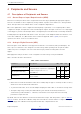
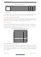
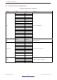
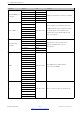

Table Of Contents
- 1 Overview
- 2 Pin Definitions
- 3 Functional Description
- 4 Peripherals and Sensors
- 4.1 Descriptions of Peripherals and Sensors
- 4.1.1 General Purpose Input / Output Interface (GPIO)
- 4.1.2 Analog-to-Digital Converter (ADC)
- 4.1.3 Hall Sensor
- 4.1.4 Digital-to-Analog Converter (DAC)
- 4.1.5 Touch Sensor
- 4.1.6 Ultra-Low-Power Co-processor
- 4.1.7 Ethernet MAC Interface
- 4.1.8 SD/SDIO/MMC Host Controller
- 4.1.9 SDIO/SPI Slave Controller
- 4.1.10 Universal Asynchronous Receiver Transmitter (UART)
- 4.1.11 I²C Interface
- 4.1.12 I²S Interface
- 4.1.13 Infrared Remote Controller
- 4.1.14 Pulse Counter
- 4.1.15 Pulse Width Modulation (PWM)
- 4.1.16 LED PWM
- 4.1.17 Serial Peripheral Interface (SPI)
- 4.1.18 Accelerator
- 4.2 Peripheral Pin Configurations
- 4.1 Descriptions of Peripherals and Sensors
- 5 Electrical Characteristics
- 6 Package Information
- 7 Part Number and Ordering Information
- 8 Learning Resources
- Appendix A – ESP32 Pin Lists
- Revision History

4 Peripherals and Sensors
• Interrupts to host for initiating data transfer
• Automatic loading of SDIO bus data and automatic discarding of padding data
• Block size of up to 512 bytes
• Interrupt vectors between the host and the slave, allowing both to interrupt each other
• Supports DMA for data transfer
4.1.10 Universal Asynchronous Receiver Transmitter (UART)
ESP32 has three UART interfaces, i.e., UART0, UART1 and UART2, which provide asynchronous
communication (RS232 and RS485) and IrDA support, communicating at a speed of up to 5 Mbps. UART
provides hardware management of the CTS and RTS signals and software flow control (XON and XOFF). All of
the interfaces can be accessed by the DMA controller or directly by the CPU.
4.1.11 I²C Interface
ESP32 has two I²C bus interfaces which can serve as I²C master or slave, depending on the user’s configuration.
The I²C interfaces support:
• Standard mode (100 Kbit/s)
• Fast mode (400 Kbit/s)
• Up to 5 MHz, yet constrained by SDA pull-up strength
• 7-bit/10-bit addressing mode
• Dual addressing mode
Users can program command registers to control I²C interfaces, so that they have more flexibility.
4.1.12 I²S Interface
Two standard I²S interfaces are available in ESP32. They can be operated in master or slave mode, in full duplex
and half-duplex communication modes, and can be configured to operate with an 8-/16-/32-/48-/64-bit
resolution as input or output channels. BCK clock frequency, from 10 kHz up to 40 MHz, is supported. When
one or both of the I²S interfaces are configured in the master mode, the master clock can be output to the
external DAC/CODEC.
Both of the I²S interfaces have dedicated DMA controllers. PDM and BT PCM interfaces are supported.
4.1.13 Infrared Remote Controller
The infrared remote controller supports eight channels of infrared remote transmission and receiving. By
programming the pulse waveform, it supports various infrared protocols. Eight channels share a 512 x 32-bit
block of memory to store the transmitting or receiving waveform.
4.1.14 Pulse Counter
The pulse counter captures pulse and counts pulse edges through seven modes. It has eight channels, each of
which captures four signals at a time. The four input signals include two pulse signals and two control signals.
When the counter reaches a defined threshold, an interrupt is generated.
Espressif Systems 35
Submit Documentation Feedback
ESP32 Series Datasheet v3.5