
Data Sheet
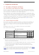
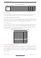

Table Of Contents
- 1 Overview
- 2 Pin Definitions
- 3 Functional Description
- 4 Peripherals and Sensors
- 4.1 Descriptions of Peripherals and Sensors
- 4.1.1 General Purpose Input / Output Interface (GPIO)
- 4.1.2 Analog-to-Digital Converter (ADC)
- 4.1.3 Hall Sensor
- 4.1.4 Digital-to-Analog Converter (DAC)
- 4.1.5 Touch Sensor
- 4.1.6 Ultra-Low-Power Co-processor
- 4.1.7 Ethernet MAC Interface
- 4.1.8 SD/SDIO/MMC Host Controller
- 4.1.9 SDIO/SPI Slave Controller
- 4.1.10 Universal Asynchronous Receiver Transmitter (UART)
- 4.1.11 I²C Interface
- 4.1.12 I²S Interface
- 4.1.13 Infrared Remote Controller
- 4.1.14 Pulse Counter
- 4.1.15 Pulse Width Modulation (PWM)
- 4.1.16 LED PWM
- 4.1.17 Serial Peripheral Interface (SPI)
- 4.1.18 Accelerator
- 4.2 Peripheral Pin Configurations
- 4.1 Descriptions of Peripherals and Sensors
- 5 Electrical Characteristics
- 6 Package Information
- 7 Part Number and Ordering Information
- 8 Learning Resources
- Appendix A – ESP32 Pin Lists
- Revision History

4 Peripherals and Sensors
4.1.7 Ethernet MAC Interface
An IEEE-802.3-2008-compliant Media Access Controller (MAC) is provided for Ethernet LAN communications.
ESP32 requires an external physical interface device (PHY) to connect to the physical LAN bus (twisted-pair, fiber,
etc.). The PHY is connected to ESP32 through 17 signals of MII or nine signals of RMII. The following features are
supported on the Ethernet MAC (EMAC) interface:
• 10 Mbps and 100 Mbps rates
• Dedicated DMA controller allowing high-speed transfer between the dedicated SRAM and Ethernet MAC
• Tagged MAC frame (VLAN support)
• Half-duplex (CSMA/CD) and full-duplex operation
• MAC control sublayer (control frames)
• 32-bit CRC generation and removal
• Several address-filtering modes for physical and multicast address (multicast and group addresses)
• 32-bit status code for each transmitted or received frame
• Internal FIFOs to buffer transmit and receive frames. The transmit FIFO and the receive FIFO are both 512
words (32-bit)
• Hardware PTP (Precision Time Protocol) in accordance with IEEE 1588 2008 (PTP V2)
• 25 MHz/50 MHz clock output
4.1.8 SD/SDIO/MMC Host Controller
An SD/SDIO/MMC host controller is available on ESP32, which supports the following features:
• Secure Digital memory (SD mem Version 3.0 and Version 3.01)
• Secure Digital I/O (SDIO Version 3.0)
• Consumer Electronics Advanced Transport Architecture (CE-ATA Version 1.1)
• Multimedia Cards (MMC Version 4.41, eMMC Version 4.5 and Version 4.51)
The controller allows up to 80 MHz clock output in three different data-bus modes: 1-bit, 4-bit and 8-bit. It
supports two SD/SDIO/MMC4.41 cards in a 4-bit data-bus mode. It also supports one SD card operating at 1.8
V.
4.1.9 SDIO/SPI Slave Controller
ESP32 integrates an SD device interface that conforms to the industry-standard SDIO Card Specification Version
2.0, and allows a host controller to access the SoC, using the SDIO bus interface and protocol. ESP32 acts as
the slave on the SDIO bus. The host can access the SDIO-interface registers directly and can access shared
memory via a DMA engine, thus maximizing performance without engaging the processor cores.
The SDIO/SPI slave controller supports the following features:
• SPI, 1-bit SDIO, and 4-bit SDIO transfer modes over the full clock range from 0 to 50 MHz
• Configurable sampling and driving clock edge
• Special registers for direct access by host
Espressif Systems 34
Submit Documentation Feedback
ESP32 Series Datasheet v3.5