
Data Sheet
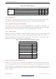
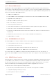
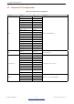
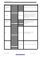

Table Of Contents
- 1 Overview
- 2 Pin Definitions
- 3 Functional Description
- 4 Peripherals and Sensors
- 4.1 Descriptions of Peripherals and Sensors
- 4.1.1 General Purpose Input / Output Interface (GPIO)
- 4.1.2 Analog-to-Digital Converter (ADC)
- 4.1.3 Hall Sensor
- 4.1.4 Digital-to-Analog Converter (DAC)
- 4.1.5 Touch Sensor
- 4.1.6 Ultra-Low-Power Co-processor
- 4.1.7 Ethernet MAC Interface
- 4.1.8 SD/SDIO/MMC Host Controller
- 4.1.9 SDIO/SPI Slave Controller
- 4.1.10 Universal Asynchronous Receiver Transmitter (UART)
- 4.1.11 I²C Interface
- 4.1.12 I²S Interface
- 4.1.13 Infrared Remote Controller
- 4.1.14 Pulse Counter
- 4.1.15 Pulse Width Modulation (PWM)
- 4.1.16 LED PWM
- 4.1.17 Serial Peripheral Interface (SPI)
- 4.1.18 Accelerator
- 4.2 Peripheral Pin Configurations
- 4.1 Descriptions of Peripherals and Sensors
- 5 Electrical Characteristics
- 6 Package Information
- 7 Part Number and Ordering Information
- 8 Learning Resources
- Appendix A – ESP32 Pin Lists
- Revision History

4 Peripherals and Sensors
Table 8: ADC Calibration Results
Parameter Description Min Max Unit
Total error
Atten=0, effective measurement range of 100 ∼ 950 mV –23 23 mV
Atten=1, effective measurement range of 100 ∼ 1250 mV –30 30 mV
Atten=2, effective measurement range of 150 ∼ 1750 mV –40 40 mV
Atten=3, effective measurement range of 150 ∼ 2450 mV –60 60 mV
4.1.3 Hall Sensor
ESP32 integrates a Hall sensor based on an N-carrier resistor. When the chip is in the magnetic field, the Hall
sensor develops a small voltage laterally on the resistor, which can be directly measured by the ADC.
4.1.4 DigitaltoAnalog Converter (DAC)
Two 8-bit DAC channels can be used to convert two digital signals into two analog voltage signal outputs. The
design structure is composed of integrated resistor strings and a buffer. This dual DAC supports power supply as
input voltage reference. The two DAC channels can also support independent conversions.
4.1.5 Touch Sensor
ESP32 has 10 capacitive-sensing GPIOs, which detect variations induced by touching or approaching the GPIOs
with a finger or other objects. The low-noise nature of the design and the high sensitivity of the circuit allow
relatively small pads to be used. Arrays of pads can also be used, so that a larger area or more points can be
detected. The 10 capacitive-sensing GPIOs are listed in Table 9.
Table 9: CapacitiveSensing GPIOs Available on ESP32
Capacitive-sensing signal name Pin name
T0 GPIO4
T1 GPIO0
T2 GPIO2
T3 MTDO
T4 MTCK
T5 MTDI
T6 MTMS
T7 GPIO27
T8 32K_XN
T9 32K_XP
4.1.6 UltraLowPower Coprocessor
The ULP processor and RTC memory remain powered on during the Deep-sleep mode. Hence, the developer
can store a program for the ULP processor in the RTC slow memory to access the peripheral devices, internal
timers and internal sensors during the Deep-sleep mode. This is useful for designing applications where the CPU
needs to be woken up by an external event, or a timer, or a combination of the two, while maintaining minimal
power consumption.
Espressif Systems 33
Submit Documentation Feedback
ESP32 Series Datasheet v3.5