
Data Sheet
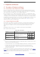
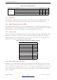
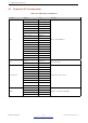
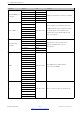

Table Of Contents
- 1 Overview
- 2 Pin Definitions
- 3 Functional Description
- 4 Peripherals and Sensors
- 4.1 Descriptions of Peripherals and Sensors
- 4.1.1 General Purpose Input / Output Interface (GPIO)
- 4.1.2 Analog-to-Digital Converter (ADC)
- 4.1.3 Hall Sensor
- 4.1.4 Digital-to-Analog Converter (DAC)
- 4.1.5 Touch Sensor
- 4.1.6 Ultra-Low-Power Co-processor
- 4.1.7 Ethernet MAC Interface
- 4.1.8 SD/SDIO/MMC Host Controller
- 4.1.9 SDIO/SPI Slave Controller
- 4.1.10 Universal Asynchronous Receiver Transmitter (UART)
- 4.1.11 I²C Interface
- 4.1.12 I²S Interface
- 4.1.13 Infrared Remote Controller
- 4.1.14 Pulse Counter
- 4.1.15 Pulse Width Modulation (PWM)
- 4.1.16 LED PWM
- 4.1.17 Serial Peripheral Interface (SPI)
- 4.1.18 Accelerator
- 4.2 Peripheral Pin Configurations
- 4.1 Descriptions of Peripherals and Sensors
- 5 Electrical Characteristics
- 6 Package Information
- 7 Part Number and Ordering Information
- 8 Learning Resources
- Appendix A – ESP32 Pin Lists
- Revision History

4 Peripherals and Sensors
4 Peripherals and Sensors
4.1 Descriptions of Peripherals and Sensors
4.1.1 General Purpose Input / Output Interface (GPIO)
ESP32 has 34 GPIO pins which can be assigned various functions by programming the appropriate registers.
There are several kinds of GPIOs: digital-only, analog-enabled, capacitive-touch-enabled, etc. Analog-enabled
GPIOs and Capacitive-touch-enabled GPIOs can be configured as digital GPIOs.
Most of the digital GPIOs can be configured as internal pull-up or pull-down, or set to high impedance. When
configured as an input, the input value can be read through the register. The input can also be set to edge-trigger
or level-trigger to generate CPU interrupts. Most of the digital IO pins are bi-directional, non-inverting and tristate,
including input and output buffers with tristate control. These pins can be multiplexed with other functions, such
as the SDIO, UART, SPI, etc. (More details can be found in the Appendix, Table IO_MUX.) For low-power
operations, the GPIOs can be set to hold their states.
4.1.2 AnalogtoDigital Converter (ADC)
ESP32 integrates 12-bit SAR ADCs and supports measurements on 18 channels (analog-enabled pins). The
ULP-coprocessor in ESP32 is also designed to measure voltage, while operating in the sleep mode, which
enables low-power consumption. The CPU can be woken up by a threshold setting and/or via other
triggers.
With appropriate settings, the ADCs can be configured to measure voltage on 18 pins maximum.
Table 7 describes the ADC characteristics.
Table 7: ADC Characteristics
Parameter Description Min Max Unit
DNL (Differential nonlinearity)
RTC controller; ADC connected to an
–7 7 LSB
external 100 nF capacitor; DC signal input;
INL (Integral nonlinearity)
ambient temperature at 25 °C;
–12 12 LSB
Wi-Fi&BT off
Sampling rate
RTC controller – 200 ksps
DIG controller – 2 Msps
Notes:
• When atten=3 and the measurement result is above 3000 (voltage at approx. 2450 mV), the ADC accuracy
will be worse than described in the table above.
• To get better DNL results, users can take multiple sampling tests with a filter, or calculate the average value.
• The input voltage range of GPIO pins within VDD3P3_RTC domain should strictly follow the DC
characteristics provided in Table 13. Otherwise, measurement errors may be introduced, and chip
performance may be affected.
By default, there are ±6% differences in measured results between chips. ESP-IDF provides couple of calibration
methods for ADC1. Results after calibration using eFuse Vref value are shown in Table 8. For higher accuracy,
users may apply other calibration methods provided in ESP-IDF, or implement their own.
Espressif Systems 32
Submit Documentation Feedback
ESP32 Series Datasheet v3.5