
Data Sheet
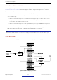
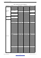
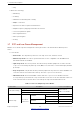
Table Of Contents
- 1 Overview
- 2 Pin Definitions
- 3 Functional Description
- 4 Peripherals and Sensors
- 4.1 Descriptions of Peripherals and Sensors
- 4.1.1 General Purpose Input / Output Interface (GPIO)
- 4.1.2 Analog-to-Digital Converter (ADC)
- 4.1.3 Hall Sensor
- 4.1.4 Digital-to-Analog Converter (DAC)
- 4.1.5 Touch Sensor
- 4.1.6 Ultra-Low-Power Co-processor
- 4.1.7 Ethernet MAC Interface
- 4.1.8 SD/SDIO/MMC Host Controller
- 4.1.9 SDIO/SPI Slave Controller
- 4.1.10 Universal Asynchronous Receiver Transmitter (UART)
- 4.1.11 I²C Interface
- 4.1.12 I²S Interface
- 4.1.13 Infrared Remote Controller
- 4.1.14 Pulse Counter
- 4.1.15 Pulse Width Modulation (PWM)
- 4.1.16 LED PWM
- 4.1.17 Serial Peripheral Interface (SPI)
- 4.1.18 Accelerator
- 4.2 Peripheral Pin Configurations
- 4.1 Descriptions of Peripherals and Sensors
- 5 Electrical Characteristics
- 6 Package Information
- 7 Part Number and Ordering Information
- 8 Learning Resources
- Appendix A – ESP32 Pin Lists
- Revision History

3 Functional Description
– Ping
• Bluetooth Low Energy
– Advertising
– Scanning
– Simultaneous advertising and scanning
– Multiple connections
– Asynchronous data reception and transmission
– Adaptive Frequency Hopping and Channel assessment
– Connection parameter update
– Data Length Extension
– Link Layer Encryption
– LE Ping
3.7 RTC and LowPower Management
With the use of advanced power-management technologies, ESP32 can switch between different power
modes.
• Power modes
– Active mode: The chip radio is powered on. The chip can receive, transmit, or listen.
– Modemsleep mode: The CPU is operational and the clock is configurable. The Wi-Fi/Bluetooth
baseband and radio are disabled.
– Lightsleep mode: The CPU is paused. The RTC memory and RTC peripherals, as well as the ULP
co-processor are running. Any wake-up events (MAC, host, RTC timer, or external interrupts) will wake
up the chip.
– Deepsleep mode: Only the RTC memory and RTC peripherals are powered on. Wi-Fi and Bluetooth
connection data are stored in the RTC memory. The ULP co-processor is functional.
– Hibernation mode: The internal 8-MHz oscillator and ULP co-processor are disabled. The RTC
recovery memory is powered down. Only one RTC timer on the slow clock and certain RTC GPIOs are
active. The RTC timer or the RTC GPIOs can wake up the chip from the Hibernation mode.
Table 6: Power Consumption by Power Modes
Power mode Description Power consumption
Active (RF working)
Wi-Fi Tx packet
Please refer to
Table 15 for details.
Wi-Fi/BT Tx packet
Wi-Fi/BT Rx and listening
Modem-sleep
The CPU is
powered on.
240 MHz
* Dual-core chip(s) 30 mA ~ 68 mA
Single-core chip(s) N/A
160 MHz
* Dual-core chip(s) 27 mA ~ 44 mA
Single-core chip(s) 27 mA ~ 34 mA
Espressif Systems 30
Submit Documentation Feedback
ESP32 Series Datasheet v3.5