
Data Sheet
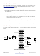
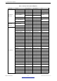
Table Of Contents
- 1 Overview
- 2 Pin Definitions
- 3 Functional Description
- 4 Peripherals and Sensors
- 4.1 Descriptions of Peripherals and Sensors
- 4.1.1 General Purpose Input / Output Interface (GPIO)
- 4.1.2 Analog-to-Digital Converter (ADC)
- 4.1.3 Hall Sensor
- 4.1.4 Digital-to-Analog Converter (DAC)
- 4.1.5 Touch Sensor
- 4.1.6 Ultra-Low-Power Co-processor
- 4.1.7 Ethernet MAC Interface
- 4.1.8 SD/SDIO/MMC Host Controller
- 4.1.9 SDIO/SPI Slave Controller
- 4.1.10 Universal Asynchronous Receiver Transmitter (UART)
- 4.1.11 I²C Interface
- 4.1.12 I²S Interface
- 4.1.13 Infrared Remote Controller
- 4.1.14 Pulse Counter
- 4.1.15 Pulse Width Modulation (PWM)
- 4.1.16 LED PWM
- 4.1.17 Serial Peripheral Interface (SPI)
- 4.1.18 Accelerator
- 4.2 Peripheral Pin Configurations
- 4.1 Descriptions of Peripherals and Sensors
- 5 Electrical Characteristics
- 6 Package Information
- 7 Part Number and Ordering Information
- 8 Learning Resources
- Appendix A – ESP32 Pin Lists
- Revision History

3 Functional Description
• balun and transmit-receive switch
• clock generator
3.4.1 2.4 GHz Receiver
The 2.4 GHz receiver demodulates the 2.4 GHz RF signal to quadrature baseband signals and converts them to
the digital domain with two high-resolution, high-speed ADCs. To adapt to varying signal channel conditions, RF
filters, Automatic Gain Control (AGC), DC offset cancelation circuits and baseband filters are integrated in the
chip.
3.4.2 2.4 GHz Transmitter
The 2.4 GHz transmitter modulates the quadrature baseband signals to the 2.4 GHz RF signal, and drives the
antenna with a high-powered Complementary Metal Oxide Semiconductor (CMOS) power amplifier. The use of
digital calibration further improves the linearity of the power amplifier, enabling state-of-the-art performance in
delivering up to +20.5 dBm of power for an 802.11b transmission and +18 dBm for an 802.11n
transmission.
Additional calibrations are integrated to cancel any radio imperfections, such as:
• Carrier leakage
• I/Q phase matching
• Baseband nonlinearities
• RF nonlinearities
• Antenna matching
These built-in calibration routines reduce the amount of time required for product testing, and render the testing
equipment unnecessary.
3.4.3 Clock Generator
The clock generator produces quadrature clock signals of 2.4 GHz for both the receiver and the transmitter. All
components of the clock generator are integrated into the chip, including all inductors, varactors, filters,
regulators and dividers.
The clock generator has built-in calibration and self-test circuits. Quadrature clock phases and phase noise are
optimized on-chip with patented calibration algorithms which ensure the best performance of the receiver and
the transmitter.
3.5 WiFi
ESP32 implements a TCP/IP and full 802.11 b/g/n Wi-Fi MAC protocol. It supports the Basic Service Set (BSS)
STA and SoftAP operations under the Distributed Control Function (DCF). Power management is handled with
minimal host interaction to minimize the active-duty period.
3.5.1 WiFi Radio and Baseband
The ESP32 Wi-Fi Radio and Baseband support the following features:
Espressif Systems 27
Submit Documentation Feedback
ESP32 Series Datasheet v3.5