
Data Sheet
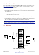
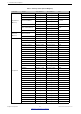
Table Of Contents
- 1 Overview
- 2 Pin Definitions
- 3 Functional Description
- 4 Peripherals and Sensors
- 4.1 Descriptions of Peripherals and Sensors
- 4.1.1 General Purpose Input / Output Interface (GPIO)
- 4.1.2 Analog-to-Digital Converter (ADC)
- 4.1.3 Hall Sensor
- 4.1.4 Digital-to-Analog Converter (DAC)
- 4.1.5 Touch Sensor
- 4.1.6 Ultra-Low-Power Co-processor
- 4.1.7 Ethernet MAC Interface
- 4.1.8 SD/SDIO/MMC Host Controller
- 4.1.9 SDIO/SPI Slave Controller
- 4.1.10 Universal Asynchronous Receiver Transmitter (UART)
- 4.1.11 I²C Interface
- 4.1.12 I²S Interface
- 4.1.13 Infrared Remote Controller
- 4.1.14 Pulse Counter
- 4.1.15 Pulse Width Modulation (PWM)
- 4.1.16 LED PWM
- 4.1.17 Serial Peripheral Interface (SPI)
- 4.1.18 Accelerator
- 4.2 Peripheral Pin Configurations
- 4.1 Descriptions of Peripherals and Sensors
- 5 Electrical Characteristics
- 6 Package Information
- 7 Part Number and Ordering Information
- 8 Learning Resources
- Appendix A – ESP32 Pin Lists
- Revision History

3 Functional Description
• One of three or four possible actions (interrupt, CPU reset, core reset, and system reset) upon the expiry of
each stage
• 32-bit expiry counter
• Write protection that prevents the RWDT and MWDT configuration from being inadvertently altered
• SPI flash boot protection
If the boot process from an SPI flash does not complete within a predetermined time period, the watchdog
will reboot the entire system.
3.3 System Clocks
3.3.1 CPU Clock
Upon reset, an external crystal clock source is selected as the default CPU clock. The external crystal clock
source also connects to a PLL to generate a high-frequency clock (typically 160 MHz).
In addition, ESP32 has an internal 8 MHz oscillator. The application can select the clock source from the external
crystal clock source, the PLL clock or the internal 8 MHz oscillator. The selected clock source drives the CPU
clock directly, or after division, depending on the application.
3.3.2 RTC Clock
The RTC clock has five possible sources:
• external low-speed (32 kHz) crystal clock
• external crystal clock divided by 4
• internal RC oscillator (typically about 150 kHz, and adjustable)
• internal 8 MHz oscillator
• internal 31.25 kHz clock (derived from the internal 8 MHz oscillator divided by 256)
When the chip is in the normal power mode and needs faster CPU accessing, the application can choose the
external high-speed crystal clock divided by 4 or the internal 8 MHz oscillator. When the chip operates in the
low-power mode, the application chooses the external low-speed (32 kHz) crystal clock, the internal RC clock or
the internal 31.25 kHz clock.
3.3.3 Audio PLL Clock
The audio clock is generated by the ultra-low-noise fractional-N PLL. More details can be found in Chapter Reset
and Clock in the ESP32 Technical Reference Manual.
3.4 Radio
The radio module consists of the following blocks:
• 2.4 GHz receiver
• 2.4 GHz transmitter
• bias and regulators
Espressif Systems 26
Submit Documentation Feedback
ESP32 Series Datasheet v3.5