
Data Sheet
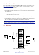
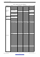
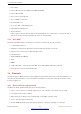
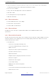
Table Of Contents
- 1 Overview
- 2 Pin Definitions
- 3 Functional Description
- 4 Peripherals and Sensors
- 4.1 Descriptions of Peripherals and Sensors
- 4.1.1 General Purpose Input / Output Interface (GPIO)
- 4.1.2 Analog-to-Digital Converter (ADC)
- 4.1.3 Hall Sensor
- 4.1.4 Digital-to-Analog Converter (DAC)
- 4.1.5 Touch Sensor
- 4.1.6 Ultra-Low-Power Co-processor
- 4.1.7 Ethernet MAC Interface
- 4.1.8 SD/SDIO/MMC Host Controller
- 4.1.9 SDIO/SPI Slave Controller
- 4.1.10 Universal Asynchronous Receiver Transmitter (UART)
- 4.1.11 I²C Interface
- 4.1.12 I²S Interface
- 4.1.13 Infrared Remote Controller
- 4.1.14 Pulse Counter
- 4.1.15 Pulse Width Modulation (PWM)
- 4.1.16 LED PWM
- 4.1.17 Serial Peripheral Interface (SPI)
- 4.1.18 Accelerator
- 4.2 Peripheral Pin Configurations
- 4.1 Descriptions of Peripherals and Sensors
- 5 Electrical Characteristics
- 6 Package Information
- 7 Part Number and Ordering Information
- 8 Learning Resources
- Appendix A – ESP32 Pin Lists
- Revision History

3 Functional Description
3.1.3 External Flash and SRAM
ESP32 supports multiple external QSPI flash and SRAM chips. More details can be found in Chapter SPI in the
ESP32 Technical Reference Manual. ESP32 also supports hardware encryption/decryption based on AES to
protect developers’ programs and data in flash.
ESP32 can access the external QSPI flash and SRAM through high-speed caches.
• Up to 16 MB of external flash can be mapped into CPU instruction memory space and read-only memory
space simultaneously.
– When external flash is mapped into CPU instruction memory space, up to 11 MB + 248 KB can be
mapped at a time. Note that if more than 3 MB + 248 KB are mapped, cache performance will be
reduced due to speculative reads by the CPU.
– When external flash is mapped into read-only data memory space, up to 4 MB can be mapped at a
time. 8-bit, 16-bit and 32-bit reads are supported.
• External SRAM can be mapped into CPU data memory space. SRAM up to 8 MB is supported and up to 4
MB can be mapped at a time. 8-bit, 16-bit and 32-bit reads and writes are supported.
Note:
After ESP32 is initialized, firmware can customize the mapping of external SRAM or flash into the CPU address space.
3.1.4 Memory Map
The structure of address mapping is shown in Figure 7. The memory and peripheral mapping of ESP32 is shown
in Table 5.
Figure 7: Address Mapping Structure
Espressif Systems 23
Submit Documentation Feedback
ESP32 Series Datasheet v3.5