
Data Sheet
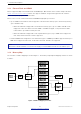
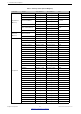
Table Of Contents
- 1 Overview
- 2 Pin Definitions
- 3 Functional Description
- 4 Peripherals and Sensors
- 4.1 Descriptions of Peripherals and Sensors
- 4.1.1 General Purpose Input / Output Interface (GPIO)
- 4.1.2 Analog-to-Digital Converter (ADC)
- 4.1.3 Hall Sensor
- 4.1.4 Digital-to-Analog Converter (DAC)
- 4.1.5 Touch Sensor
- 4.1.6 Ultra-Low-Power Co-processor
- 4.1.7 Ethernet MAC Interface
- 4.1.8 SD/SDIO/MMC Host Controller
- 4.1.9 SDIO/SPI Slave Controller
- 4.1.10 Universal Asynchronous Receiver Transmitter (UART)
- 4.1.11 I²C Interface
- 4.1.12 I²S Interface
- 4.1.13 Infrared Remote Controller
- 4.1.14 Pulse Counter
- 4.1.15 Pulse Width Modulation (PWM)
- 4.1.16 LED PWM
- 4.1.17 Serial Peripheral Interface (SPI)
- 4.1.18 Accelerator
- 4.2 Peripheral Pin Configurations
- 4.1 Descriptions of Peripherals and Sensors
- 5 Electrical Characteristics
- 6 Package Information
- 7 Part Number and Ordering Information
- 8 Learning Resources
- Appendix A – ESP32 Pin Lists
- Revision History

3 Functional Description
3 Functional Description
This chapter describes the functions integrated in ESP32.
3.1 CPU and Memory
3.1.1 CPU
ESP32 contains one or two low-power Xtensa
®
32-bit LX6 microprocessor(s) with the following features:
• 7-stage pipeline to support the clock frequency of up to 240 MHz (160 MHz for ESP32-S0WD,
ESP32-D2WD, and ESP32-U4WDH)
• 16/24-bit Instruction Set provides high code-density
• Support for Floating Point Unit
• Support for DSP instructions, such as a 32-bit multiplier, a 32-bit divider, and a 40-bit MAC
• Support for 32 interrupt vectors from about 70 interrupt sources
The single-/dual-CPU interfaces include:
• Xtensa RAM/ROM Interface for instructions and data
• Xtensa Local Memory Interface for fast peripheral register access
• External and internal interrupt sources
• JTAG for debugging
3.1.2 Internal Memory
ESP32’s internal memory includes:
• 448 KB of ROM for booting and core functions
• 520 KB of on-chip SRAM for data and instructions
• 8 KB of SRAM in RTC, which is called RTC FAST Memory and can be used for data storage; it is accessed
by the main CPU during RTC Boot from the Deep-sleep mode.
• 8 KB of SRAM in RTC, which is called RTC SLOW Memory and can be accessed by the co-processor
during the Deep-sleep mode.
• 1 Kbit of eFuse: 256 bits are used for the system (MAC address and chip configuration) and the remaining
768 bits are reserved for customer applications, including flash-encryption and chip-ID.
• Embedded flash
Note:
Products in the ESP32 series differ from each other, in terms of their support for embedded flash and the size of it. For
details, please refer to Section 7 Part Number and Ordering Information.
Espressif Systems 22
Submit Documentation Feedback
ESP32 Series Datasheet v3.5