
Data Sheet
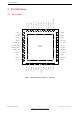
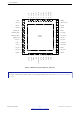
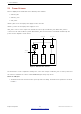
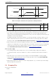
Table Of Contents
- 1 Overview
- 2 Pin Definitions
- 3 Functional Description
- 4 Peripherals and Sensors
- 4.1 Descriptions of Peripherals and Sensors
- 4.1.1 General Purpose Input / Output Interface (GPIO)
- 4.1.2 Analog-to-Digital Converter (ADC)
- 4.1.3 Hall Sensor
- 4.1.4 Digital-to-Analog Converter (DAC)
- 4.1.5 Touch Sensor
- 4.1.6 Ultra-Low-Power Co-processor
- 4.1.7 Ethernet MAC Interface
- 4.1.8 SD/SDIO/MMC Host Controller
- 4.1.9 SDIO/SPI Slave Controller
- 4.1.10 Universal Asynchronous Receiver Transmitter (UART)
- 4.1.11 I²C Interface
- 4.1.12 I²S Interface
- 4.1.13 Infrared Remote Controller
- 4.1.14 Pulse Counter
- 4.1.15 Pulse Width Modulation (PWM)
- 4.1.16 LED PWM
- 4.1.17 Serial Peripheral Interface (SPI)
- 4.1.18 Accelerator
- 4.2 Peripheral Pin Configurations
- 4.1 Descriptions of Peripherals and Sensors
- 5 Electrical Characteristics
- 6 Package Information
- 7 Part Number and Ordering Information
- 8 Learning Resources
- Appendix A – ESP32 Pin Lists
- Revision History

2 Pin Definitions
VDD
CHIP_PU
t
0
t
1
V
IL_nRST
VDD3P3_RTC Min
Figure 5: ESP32 Powerup and Reset Timing
Table 2: Description of ESP32 Powerup and Reset Timing Parameters
Parameters Description Min. Unit
t
0
Time between the 3.3 V rails being brought up and CHIP_PU being
activated
50 µs
t
1
Duration of CHIP_PU signal level < V
IL_nRST
(refer to its value in
Table 13 DC Characteristics) to reset the chip
50 µs
• In scenarios where ESP32 is powered on and off repeatedly by switching the power rails, while there is a
large capacitor on the VDD33 rail and CHIP_PU and VDD33 are connected, simply switching off the
CHIP_PU power rail and immediately switching it back on may cause an incomplete power discharge cycle
and failure to reset the chip adequately.
An additional discharge circuit may be required to accelerate the discharge of the large capacitor on rail
VDD33, which will ensure proper power-on-reset when the ESP32 is powered up again. Please find the
discharge circuit in Figure ESP32WROOM32 Peripheral Schematics, in ESP32-WROOM-32 Datasheet.
• When a battery is used as the power supply for the ESP32 series of chips and modules, a supply voltage
supervisor is recommended, so that a boot failure due to low voltage is avoided. Users are recommended
to pull CHIP_PU low if the power supply for ESP32 is below 2.3 V. For the reset circuit, please refer to
Figure ESP32WROOM32 Peripheral Schematics, in ESP32-WROOM-32 Datasheet.
Notes on power supply:
• The operating voltage of ESP32 ranges from 2.3 V to 3.6 V. When using a single-power supply, the
recommended voltage of the power supply is 3.3 V, and its recommended output current is 500 mA or
more.
• When VDD_SDIO 1.8 V is used as the power supply for external flash/PSRAM, a 2-kohm grounding
resistor should be added to VDD_SDIO. For the circuit design, please refer to Figure ESP32WROVER
Schematics, in ESP32-WROVER Datasheet.
• When the three digital power supplies are used to drive peripherals, e.g., 3.3 V flash, they should comply
with the peripherals’ specifications.
2.4 Strapping Pins
There are five strapping pins:
• MTDI
Espressif Systems 19
Submit Documentation Feedback
ESP32 Series Datasheet v3.5