
Data Sheet
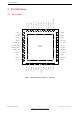
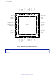
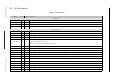
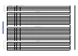
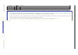
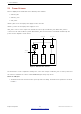
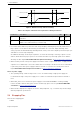
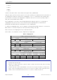
Table Of Contents
- 1 Overview
- 2 Pin Definitions
- 3 Functional Description
- 4 Peripherals and Sensors
- 4.1 Descriptions of Peripherals and Sensors
- 4.1.1 General Purpose Input / Output Interface (GPIO)
- 4.1.2 Analog-to-Digital Converter (ADC)
- 4.1.3 Hall Sensor
- 4.1.4 Digital-to-Analog Converter (DAC)
- 4.1.5 Touch Sensor
- 4.1.6 Ultra-Low-Power Co-processor
- 4.1.7 Ethernet MAC Interface
- 4.1.8 SD/SDIO/MMC Host Controller
- 4.1.9 SDIO/SPI Slave Controller
- 4.1.10 Universal Asynchronous Receiver Transmitter (UART)
- 4.1.11 I²C Interface
- 4.1.12 I²S Interface
- 4.1.13 Infrared Remote Controller
- 4.1.14 Pulse Counter
- 4.1.15 Pulse Width Modulation (PWM)
- 4.1.16 LED PWM
- 4.1.17 Serial Peripheral Interface (SPI)
- 4.1.18 Accelerator
- 4.2 Peripheral Pin Configurations
- 4.1 Descriptions of Peripherals and Sensors
- 5 Electrical Characteristics
- 6 Package Information
- 7 Part Number and Ordering Information
- 8 Learning Resources
- Appendix A – ESP32 Pin Lists
- Revision History

2 Pin Definitions
Name No. Type Function
CAP1 48 I Connects to a 10 nF series capacitor to ground
GND 49 P Ground
Note:
• The pin-pin mapping between ESP32-D2WD/ESP32-U4WDH and the embedded flash is as follows: GPIO16 = CS#, GPIO17 = IO1/DO, SD_CMD = IO3/HOLD#, SD_CLK =
CLK, SD_DATA_0 = IO2/WP#, SD_DATA_1 = IO0/DI. The pins used for embedded flash are not recommended for other uses.
• In most cases, the data port connection between ESP32 series of chips other than ESP32-D2WD/ESP32-U4WDH and external flash is as follows: SD_DATA0/SPIQ = IO1/DO,
SD_DATA1/SPID = IO0/DI, SD_DATA2/SPIHD = IO3/HOLD#, SD_DATA3/SPIWP = IO2/WP#.
• For a quick reference guide to using the IO_MUX, Ethernet MAC, and GIPO Matrix pins of ESP32, please refer to Appendix ESP32 Pin Lists.
Espressif Systems 17
Submit Documentation Feedback
ESP32 Series Datasheet v3.5