
Data Sheet
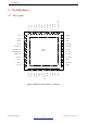
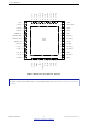
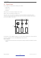
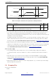
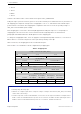
Table Of Contents
- 1 Overview
- 2 Pin Definitions
- 3 Functional Description
- 4 Peripherals and Sensors
- 4.1 Descriptions of Peripherals and Sensors
- 4.1.1 General Purpose Input / Output Interface (GPIO)
- 4.1.2 Analog-to-Digital Converter (ADC)
- 4.1.3 Hall Sensor
- 4.1.4 Digital-to-Analog Converter (DAC)
- 4.1.5 Touch Sensor
- 4.1.6 Ultra-Low-Power Co-processor
- 4.1.7 Ethernet MAC Interface
- 4.1.8 SD/SDIO/MMC Host Controller
- 4.1.9 SDIO/SPI Slave Controller
- 4.1.10 Universal Asynchronous Receiver Transmitter (UART)
- 4.1.11 I²C Interface
- 4.1.12 I²S Interface
- 4.1.13 Infrared Remote Controller
- 4.1.14 Pulse Counter
- 4.1.15 Pulse Width Modulation (PWM)
- 4.1.16 LED PWM
- 4.1.17 Serial Peripheral Interface (SPI)
- 4.1.18 Accelerator
- 4.2 Peripheral Pin Configurations
- 4.1 Descriptions of Peripherals and Sensors
- 5 Electrical Characteristics
- 6 Package Information
- 7 Part Number and Ordering Information
- 8 Learning Resources
- Appendix A – ESP32 Pin Lists
- Revision History

2 Pin Definitions
2 Pin Definitions
2.1 Pin Layout
32K_XP 12
VDET_2 11
10
9
8
7
6
5
4
3
2
1
VDET_1
CHIP_PU
SENSOR_VN
SENSOR_CAPN
SENSOR_CAPP
SENSOR_VP
VDD3P3
VDD3P3
LNA_IN
VDDA
25
26
27
28
29
30
31
32
33
34
35
36
GPIO16
VDD_SDIO
GPIO5
VDD3P3_CPU37
GPIO1938
39
40
41
42
43
44
45
46
47
48
GPIO22
U0RXD
U0TXD
GPIO21
XTAL_N
XTAL_P
VDDA
CAP2
CAP1
GPIO2
24
MTDO
23
22
21
20
19
18
17
16
15
14
13
MTCK
VDD3P3_RTC
MTDI
MTMS
GPIO27
GPIO26
GPIO25
32K_XN
SD_DATA_2
SD_DATA_3
SD_CMD
SD_CLK
SD_DATA_0
SD_DATA_1
GPIO4
GPIO0
GPIO23
GPIO18
VDDA
GPIO17
ESP32
49 GND
Figure 2: ESP32 Pin Layout (QFN 6*6, Top View)
Espressif Systems 13
Submit Documentation Feedback
ESP32 Series Datasheet v3.5