
Data Sheet
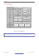
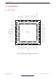
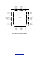
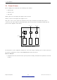
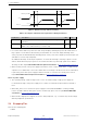
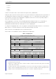
Table Of Contents
- 1 Overview
- 2 Pin Definitions
- 3 Functional Description
- 4 Peripherals and Sensors
- 4.1 Descriptions of Peripherals and Sensors
- 4.1.1 General Purpose Input / Output Interface (GPIO)
- 4.1.2 Analog-to-Digital Converter (ADC)
- 4.1.3 Hall Sensor
- 4.1.4 Digital-to-Analog Converter (DAC)
- 4.1.5 Touch Sensor
- 4.1.6 Ultra-Low-Power Co-processor
- 4.1.7 Ethernet MAC Interface
- 4.1.8 SD/SDIO/MMC Host Controller
- 4.1.9 SDIO/SPI Slave Controller
- 4.1.10 Universal Asynchronous Receiver Transmitter (UART)
- 4.1.11 I²C Interface
- 4.1.12 I²S Interface
- 4.1.13 Infrared Remote Controller
- 4.1.14 Pulse Counter
- 4.1.15 Pulse Width Modulation (PWM)
- 4.1.16 LED PWM
- 4.1.17 Serial Peripheral Interface (SPI)
- 4.1.18 Accelerator
- 4.2 Peripheral Pin Configurations
- 4.1 Descriptions of Peripherals and Sensors
- 5 Electrical Characteristics
- 6 Package Information
- 7 Part Number and Ordering Information
- 8 Learning Resources
- Appendix A – ESP32 Pin Lists
- Revision History

1 Overview
1.6 Block Diagram
Core and memory
ROM
Cryptographic hardware
acceleration
AES
SHA RSA
RTC
ULP
coprocessor
Recovery
memory
PMU
Bluetooth
link
controller
Bluetooth
baseband
Wi-Fi MAC
Wi-Fi
baseband
SPI
2 or 1 x Xtensa® 32-
bit LX6 Microprocessors
RF
receive
RF
transmit
Switch
Balun
I2C
I2S
SDIO
UART
TWAI®
ETH
IR
PWM
Touch sensor
DAC
ADC
Clock
generator
RNG
SRAM
Embedded Flash
Figure 1: Functional Block Diagram
Note:
Products in the ESP32 series differ from each other in terms of their support for embedded flash and the number of CPUs
they have. For details, please refer to Section 7 Part Number and Ordering Information.
Espressif Systems 12
Submit Documentation Feedback
ESP32 Series Datasheet v3.5