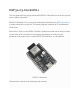
ESP32-C3-DevKitM-1 This user guide will help you get started with ESP32-C3-DevKitM-1 and will also provide more in-depth information. ESP32-C3-DevKitM-1 is an entry-level development board based on ESP32-C3-MINI-1, a module named for its small size. This board integrates complete Wi-Fi and Bluetooth LE functions. Most of the I/O pins on the ESP32-C3-MINI-1 module are broken out to the pin headers on both sides of this board for easy interfacing.
• • • • Getting Started: Overview of ESP32-C3-DevKitM-1 and hardware/software setup instructions to get started. Hardware Reference: More detailed information about the ESP32-C3DevKitM-1’s hardware. Hardware Revision Details: Revision history, known issues, and links to user guides for previous versions (if any) of ESP32-C3-DevKitM-1. Related Documents: Links to related documentation.
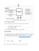
Key Component Description is ESP32-C3FN4, a chip that has an embedded flash of 4 MB. Since flash is packaged in the ESP32-C3FN4 chip, rather than integrated into the module, ESP32-C3-MINI-1 has a smaller package size. 5 V to 3.3 V LDO Power regulator that converts a 5 V supply into a 3.3 V output. 5 V Power On LED Turns on when the USB power is connected to the board. Pin Headers All available GPIO pins (except for the SPI bus for flash) are broken out to the pin headers on the board.
Please proceed to Get Started, where Section Installation Step by Step will quickly help you set up the development environment and then flash an application example onto your ESP32-C3-DevKitM-1. Contents and Packaging Retail Orders If you order one or several samples, each ESP32-C3-DevKitM-1 comes in an individual package in either antistatic bag or any packaging depending on your retailer. For retail orders, please go to https://www.espressif.com/en/company/contact/buy-asample.
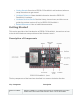
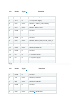
ESP32-C3-DevKitM-1 (click to enlarge) Power Supply Options There are three mutually exclusive ways to provide power to the board: Micro-USB Port, default power supply • 5V and GND pin headers • 3V3 and GND pin headers It is recommended to use the first option: Micro-USB Port. • Header Block The two tables below provide the Name and Function of the pin headers on both sides of the board (J1 and J3). The pin header names are shown in ESP32-C3-DevKitM-1 front.
No. Name Type 1 Function 2 3V3 P 3.3 V power supply 3 3V3 P 3.3 V power supply 4 IO2 I/O/T GPIO2 2, ADC1_CH2, FSPIQ 5 IO3 I/O/T GPIO3, ADC1_CH3 6 GND G Ground 7 RST I CHIP_PU 8 GND G Ground 9 IO0 I/O/T GPIO0, ADC1_CH0, XTAL_32K_P 10 IO1 I/O/T GPIO1, ADC1_CH1, XTAL_32K_N 11 IO10 I/O/T GPIO10, FSPICS0 12 GND G Ground 13 5V P 5 V power supply 14 5V P 5 V power supply 15 GND G Ground No.
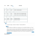
No. Name Type 1 Function 7 GND G Ground 8 IO7 I/O/T GPIO7, FSPID, MTDO 9 IO6 I/O/T GPIO6, FSPICLK, MTCK 10 IO5 I/O/T GPIO5, ADC2_CH0, FSPIWP, MTDI 11 IO4 I/O/T GPIO4, ADC1_CH4, FSPIHD, MTMS 12 GND G Ground 13 IO18 I/O/T GPIO18, USB_D- 14 IO19 I/O/T GPIO19, USB_D+ 15 GND G Ground 1(1,2) P: Power supply; I: Input; O: Output; T: High impedance. 2(1,2,3) GPIO2, GPIO8, and GPIO9 are strapping pins of the ESP32-C3FN4 chip.
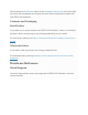
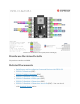
ESP32-C3-DevKitM-1 Pin Layout (click to enlarge) Hardware Revision Details No previous versions available.