
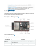
Datasheet

No.
Name
Type 1
Function
14
5V
P
5 V power supply
15
G
G
Ground
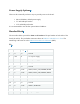
J3
No.
Name
Type 1
Function
1
G
G
Ground
2
0
I/O/T
GPIO0, ADC1_CH0, XTAL_32K_P
3
1
I/O/T
GPIO1, ADC1_CH1, XTAL_32K_N
4
2
I/O/T
GPIO2 2, ADC1_CH2, FSPIQ
5
3
I/O/T
GPIO3, ADC1_CH3
6
G
G
Ground
7
10
I/O/T
GPIO10, FSPICS0
8
G
G
Ground
9
RX
I/O/T
GPIO20, U0RXD
10
TX
I/O/T
GPIO21, U0TXD
11
G
G
Ground
12
18
I/O/T
GPIO18
13
19
I/O/T
GPIO19
14
G
G
Ground
15
G
G
Ground
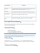
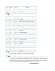
1(1,2)
P: Power supply; I: Input; O: Output; T: High impedance.
2(1,2,3)
GPIO2, GPIO8, and GPIO9 are strapping pins of the ESP32-C3 chip. These pins are used
to control several chip functions depending on binary voltage values applied to the pins
during chip power-up or system reset. For description and application of the strapping
pins, please refer to Section Strapping Pins in ESP32-C3 Datasheet.