
Datasheet
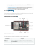
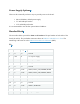
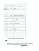

Key Component
Description
5 V Power On LED
Turns on when the USB power is connected to the board.
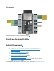
Pin Headers
All available GPIO pins (except for the SPI bus for flash) are broken out to the
pin headers on the board. For details, please see Header Block.
Boot Button
Download button. Holding down Boot and then pressing Reset initiates
Firmware Download mode for downloading firmware through the serial port.
Micro-USB Port
USB interface. Power supply for the board as well as the communication
interface between a computer and the ESP32-C3 chip.
Reset Button
Press this button to restart the system.
USB-to-UART
Bridge
Single USB-to-UART bridge chip provides transfer rates up to 3 Mbps.
RGB LED
Addressable RGB LED, driven by GPIO8.
Start Application Development
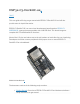
Before powering up your ESP32-C3-DevKitC-02, please make sure that it is in good condition
with no obvious signs of damage.
Required Hardware
• ESP32-C3-DevKitC-02
• USB 2.0 cable (Standard-A to Micro-B)
• Computer running Windows, Linux, or macOS
Note
Be sure to use an appropriate USB cable. Some cables are for charging only and do not provide
the needed data lines nor work for programming the boards.
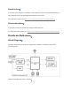
Software Setup
Please proceed to Get Started, where Section Installation will quickly help you set up the
development environment and then flash an application example into your ESP32-C3-DevKitC-
02.
Contents and Packaging