
Data Sheet
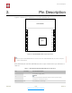

Table Of Contents

!
3. Functional Description
3.3. Crystal Oscillator
ESP-WROOM-02U and ESP-WROOM-02D use a 26-MHz crystal oscillator. The accuracy
of the crystal oscillator should be ±10 PPM.
When using the download tool, please select the right type of crystal oscillator. In circuit
design, capacitors C1 and C2 which connect to the earth are added to the input and
output terminals of the crystal oscillator respectively. The values of the two capacitors can
be flexible, ranging from 6 pF to 22 pF, however, the specific capacitive values depend on
further testing of, and adjustment to, the overall performance of the whole circuit. Normally,
the capacitive values of C1 and C2 are within 10 pF for the 26-MHz crystal oscillator.
3.4. Interface Description
Table 3-1. Interface Description
Interface
Pin
Functional Description
HSPI
IO12 (MISO), IO13
(MOSI), IO14 (CLK),
IO15 (CS)
Connects to SPI Flash, display screen, and MCU.
PWM
IO12 (R), IO15
(G),IO13 (B)
Currently the PWM interface has four channels, but users can extend it
to eight channels. PWM interface can realize the control of LED lights,
buzzers, relays, electronic machines, etc.
IR
IO14 (IR_T), IO5
(IR_R)
The functionality of the infrared remote control interface can be realized
via software programming. The interface uses NEC coding, modulation,
and demodulation. The frequency of the modulated carrier signal is 38
kHz.
ADC
TOUT
Tests the power supply voltage of VDD3P3 (Pin3 and Pin4) and the input
power voltage of TOUT (Pin6). However, these two functions cannot be
used simultaneously. This interface is typically used in sensors.
I2C
IO14 (SCL), IO2 (SDA)
Connects to external sensors and display screens, etc.
UART
UART0: TXD
(U0TXD),
RXD (U0RXD), IO15
(RTS), IO13 (CTS)
UART1: IO2 (TXD)
Communicates with the UART device.
Downloading: U0TXD + U0RXD or GPIO2 + U0RXD
Communicating: (UART0): U0TXD, U0RXD, MTDO (U0RTS), MTCK
(U0CTS)
Debugging: UART1_TXD (GPIO2) can be used to print debugging
information.
By default, UART0 will output some printed information when you power
on ESP8266EX. If this issue influences some specific applications, users
can exchange the inner pins of UART when initializing ESP8266EX, that
is, exchange U0TXD and U0RXD with U0RTS and U0CTS. Users can
connect MTDO and MTCK to the serial port of the external MCU to
realize the communication.
Espressif
! /! 6 22
Submit Documentation Feedback
2020.07