
Data Sheet
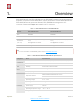
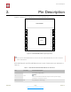

Table Of Contents

!
2. Pin Description
2. Pin Description
Figure 2-1 shows the pin distribution of the ESP-WROOM-02D.
!
Figure 2-1. ESP-WROOM-02D Pin Layout (Top View)
ESP-WROOM-02D and ESP-WROOM-02U have 18 pins. Please see the pin definitions in
Table 2-1.
19GND
PCB ANTENNA
GND
IO16
TOUT
RST
IO5
GND
TXD
RXD
IO4
3V3
EN
IO14
IO12
IO13
IO15
IO2
IO0
GND
9
8
7
6
5
4
3
2
1
10
11
12
13
14
15
16
17
18
📖 Note:
The pin layout of ESP-WROOM-02U is the same with that of ESP-WROOM-02D, but it has no keepout
zone for PCB antenna.
Table 2-1. ESP-WROOM-02U/ESP-WROOM-02D Pin Definitions
No.
Pin Name
Functional Description
1
3V3
3.3 V power supply (VDD)
📖 Note:
It is recommended the maximum output current a power supply
provides be of 500 mA or above.
2
EN
Chip enable pin. Active high.
Espressif
! /! 3 22
Submit Documentation Feedback
2020.07