ESP-WROOM-02D/02U Datasheet Includes: ESP-WROOM-02D ESP-WROOM-02U Version 1.7 Espressif Systems Copyright © 2020 www.espressif.
About This Guide This document provides introduction to the specifications of ESP-WROOM-02D and ESPWROOM-02U hardware. Release Notes Date Version Release notes 2017.11 V1.0 First release. 2018.03 V1.1 Updated the figure of ESP-WROOM-02U dimensions. • Updated Table 1-1 and Table 1-2; 2018.08 V1.2 • Updated module dimensions; • Added PCB pattern; • Updated document cover. 2019.04 V1.3 2019.08 V1.4 2019.12 V1.5 2019.12 V1.6 2020.07 V1.
Table of Contents 1. Overview ................................................................................................................................ 1 2. Pin Description ......................................................................................................................3 3. Functional Description ..........................................................................................................5 3.1. CPU .....................................................................
1. Overview ! 1. Overview ESP-WROOM-02D and ESP-WROOM-02U are ESP8266EX-based modules developed by Espressif. Compared to ESP-WROOM-02, the RF performance of ESP-WROOM-02D and ESP-WROOM-02U are optimized. Besides, ESP-WROOM-02U integrates a U.FL connector. Please see Chapter 8 for details of U.FL connector. Table 1-1. ESP-WROOM-02D vs. ESP-WROOM-02U Module ESP-WROOM-02D ESP-WROOM-02U Core ESP8266 ESP8266 Antenna Onboard antenna IPEX antenna Dimensions (18.00 ± 0.10) x (20.00 ± 0.10) x (3.20 ± 0.
1.
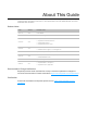
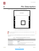
2. Pin Description ! 2. Pin Description Figure 2-1 shows the pin distribution of the ESP-WROOM-02D. PCB ANTENNA 1 3V3 GND 18 2 EN IO16 17 3 IO14 TOUT 16 4 IO12 RST 15 5 IO13 IO5 14 6 IO15 GND 13 7 IO2 TXD 12 8 IO0 RXD 11 9 GND IO4 10 19 GND ! Figure 2-1. ESP-WROOM-02D Pin Layout (Top View) 📖 Note: The pin layout of ESP-WROOM-02U is the same with that of ESP-WROOM-02D, but it has no keepout zone for PCB antenna. ESP-WROOM-02D and ESP-WROOM-02U have 18 pins.
2. Pin Description ! No. Pin Name Functional Description 3 IO14 GPIO14; HSPI_CLK 4 IO12 GPIO12; HSPI_MISO 5 IO13 GPIO13; HSPI_MOSI; UART0_CTS 6 IO15 7 IO2 8 IO0 GPIO15; MTDO; HSPICS; UART0_RTS Pull down. GPIO2; UART1_TXD Floating (internal pull-up) or pull up. GPIO0 • UART download: pull down. • Flash boot: floating or pull up.
3. Functional Description ! 3. Functional Description 3.1. CPU The ESP8266EX integrates a Tensilica L106 32-bit RISC processor, which achieves extralow power consumption and reaches a maximum clock speed of 160 MHz. The Real-Time Operating System (RTOS) and Wi-Fi stack allow 80% of the processing power to be available for user application programming and development.
3. Functional Description ! 3.3. Crystal Oscillator ESP-WROOM-02U and ESP-WROOM-02D use a 26-MHz crystal oscillator. The accuracy of the crystal oscillator should be ±10 PPM. When using the download tool, please select the right type of crystal oscillator. In circuit design, capacitors C1 and C2 which connect to the earth are added to the input and output terminals of the crystal oscillator respectively.
3. Functional Description ! Interface Pin Functional Description I2S input: IO12 (I2SI_DATA) ; IO13 (I2SI_BCK ); I2S IO14 (I2SI_WS); Collects, processes and transmits audio data. I2S output: IO15 (I2SO_BCK ); IO3 (I2SO_DATA); IO2 (I2SO_WS ). Espressif !7/!22 Submit Documentation Feedback 2020.
4. Electrical Characteristics ! 4. Electrical Characteristics 📖 Note: Unless otherwise specified, measurements are based on VDD = 3.3 V, TA = 25 °C. 4.1. Electrical Characteristics Table 4-1. Electrical Characteristics Parameter Symbol Min Typ Max Unit Operating temperature - –40 20 85 ℃ Maximum soldering temperature (Condition: IPC/JEDEC J-STD-020) - - - 260 ℃ Supply voltage VDD 2.7 3.3 3.6 V Input logic level low VIL –0.3 - 0.25 VDD V Input logic level high VIH 0.
4. Electrical Characteristics ! Description Min Typ Max Unit 6 Mbps (1/2 BPSK) - –93 - dBm 54 Mbps (3/4 64-QAM) - –75 - dBm HT20, MCS7 (65 Mbps, 72.2 Mbps) - –72 - dBm Adjacent channel rejection OFDM, 6 Mbps - 37 - dB OFDM, 54 Mbps - 21 - dB HT20, MCS0 - 37 - dB HT20, MCS7 - 20 - dB 📖 Note: For the module that uses an IPEX antenna, the output impedance is 50 Ω. 4.3. Power Consumption The following power consumption data were obtained from the tests with a 3.
4. Electrical Characteristics ! 📖 Notes: ① Modem-sleep is used when such applications as PWM or I2S require the CPU to be working. In cases where Wi-Fi connectivity is maintained and data transmission is not required, the Wi-Fi Modem circuit can be shut down to save power, according to 802.11 standards (such as U-APSD). For example, in DTIM3, when ESP8266EX sleeps for 300 ms and wakes up for 3 ms to receive Beacon packages from AP, the overall average current consumption is about 15 mA.
4. Electrical Characteristics ! 📖 Note: Solder the module in a single reflow. If the PCBA requires multiple reflows, place the module on the PCB during the final reflow. 4.5. Electrostatic Discharge Table 4-4.
A B C 5 1 GND CON1 J10 J9 CON1 CON1 CON1 J11 GPIO0 CON1 J12 CON1 J13 CON1 1 GPIO2 GPIO15 J8 1 1 CON1 CON1 J7 CON1 J6 J14 GPIO13 J5 1 CON1 CON1 GPIO12 J15 J4 1 CON1 CON1 J16 GPIO14 J3 1 CON1 CON1 J17 CH_PU J2 1 D1 LESD8D3.3CAT5G J18 VDD33 CON1 1 CON1 J1 1 1 1 1 1 1 1 1 1 GPIO4 URXD UTXD GND GPIO5 RST TOUT GPIO16 GND 4 ANT1 1 2 GND C3 0.1uF L3 4.
A B C ! 5 1 GND CON1 J10 J9 CON1 CON1 CON1 GPIO0 J11 1 J8 GPIO2 CON1 J12 CON1 1 GPIO15 CON1 J13 CON1 CON1 J7 1 GPIO13 J14 1 J5 CON1 J6 CON1 CON1 GPIO12 J15 1 J4 GPIO14 CON1 1 J16 J3 CON1 CON1 1 CON1 J17 J2 CH_PU CON1 1 D1 LESD8D3.3CAT5G J18 VDD33 CON1 J1 GND 1 1 1 1 1 1 1 1 1 GPIO4 URXD UTXD GND GPIO5 RST TOUT GPIO16 GND 4 CON1 IPEX GND C3 0.1uF GND GND C7 0.1uF(NC) L3 4.
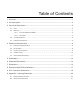
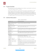
6. Peripheral Schematics ! 6. Peripheral Schematics VDD33 VDD33 C1 10uF GND C3 GND R2 0.1uF 10K GND U1 EN IO14 IO12 IO13 IO15 IO2 IO0 1 2 3 4 5 6 7 8 9 3V3 EN IO14 IO12 IO13 IO15 IO2 IO0 GND1 P_GND GND3 IO16 TOUT RST IO5 GND2 TXD RXD IO4 19 18 17 16 15 14 13 12 11 10 UART DOWNLOAD J1 IO16 ADC RST IO5 TXD RXD IO4 GND 1 2 GND GND 3 2 1 C2 0.1uF R1 10K J2 BOOT OPTION GND ! Figure 6-1. ESP-WROOM-02D/ESP-WROOM-02U Peripheral Schematics 📖 Note: 1.
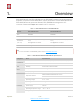
Module Width !15/! 22 Submit Documentation Feedback 0.90±0.10 Top View 15.70±0.10 0 0.90±0.10 0.45±0.10 Side View PCB Thickness 0.80±0.10 Module Thickness 3.20±0.10 0.90±0.10 4.30±0.10 4.00±0.10 0.90±0.10 Bottom View 6.00±0.10 4.00±0.10 18.00±0.10 12.00±0.10 1.50±0.10 0.85±0.1 Unit: mm 7. 1.50±0.10 18.00±0.10 Antenna Area 0.1 6.00±0.10 12.00±0.10 Module Length 0± Espressif 20.00±0.10 ! 0.5 ESP-WROOM-02D DIMENSIONS 7. Dimensions ! Dimensions Figure 7-1.
Module Width !16/! 22 Submit Documentation Feedback 12.75±0.10 Top View 0.90±0.10 0.45±0.10 18.00±0.10 15.70±0.10 11.50±0.10 Module Length 8.85±0.10 Espressif Side View 1.50±0.10 3.00±0.10 2.80±0.10 0.90±0.10 PCB Thickness 0.80±0.10 Module Thickness 3.20±0.10 14.30±0.10 ! 12.00±0.10 ESP-WROOM-02U DIMENSIONS 8.12±0.10 Bottom View 4.37±0.10 3.90±0.10 0.90±0.10 18.00±0.10 0.85±0.1 Unit: mm 7. Dimensions ! Figure 7-2. ESP-WROOM-02U Dimensions 2020.07 3.94±0.10 14.30±0.
8. Recommended PCB Land Pattern ! 8. Recommended PCB Land Pattern 6 7.1 Unit:mm 9 1.5 18 4 17.5 18 10 0.9 7.1 4.29 4 1.5x8=12 20 1 ! Figure 8-1. Recommended PCB Land Pattern of ESP-WROOM-02D Espressif !17/! 22 Submit Documentation Feedback 2020.
8. Recommended PCB Land Pattern ! 1.4 Unit:mm 1.5 4 9 17.5 18 10 0.9 7.1 18 4.29 4 1.5x8=12 14.3 1 ! Figure 8-2. Recommended PCB Land Pattern of ESP-WROOM-02U Espressif !18/! 22 Submit Documentation Feedback 2020.
9. U.FL Connector Dimensions ! 9. U.FL Connector Dimensions Unit: mm ! Figure 8-1. Dimensions of ESP-WROOM-02U’s U.FL Connector Espressif !19/! 22 Submit Documentation Feedback 2020.
Appendix A ! A. Appendix—Learning Resources A.1. Must-Read Documents • ESP8266 Quick Start Guide Description: This document is a quick user guide to getting started with ESP8266. It includes an introduction to the ESP-LAUNCHER, how to download firmware on to the board and run it, how to compile the AT application, structure and the debugging method of RTOS SDK. Basic documentation and other related resources for the ESP8266 are also provided.
Appendix A ! • FAQ A.2. Must-Have Resources • ESP8266 SDKs Description: This website page provides links to the latest version of ESP8266 SDK and the older ones. • ESP8266 Tools Description: This website page provides links to the ESP8266 flash download tools and ESP8266 performance evaluation tools. • ESP8266 App • ESP8266 Certification and Test Guide • ESP8266 BBS • ESP8266 Resources Espressif !21/! 22 Submit Documentation Feedback 2020.
Disclaimer and Copyright Notice Information in this document, including URL references, is subject to change without notice. THIS DOCUMENT IS PROVIDED AS IS WITH NO WARRANTIES WHATSOEVER, INCLUDING ANY WARRANTY OF MERCHANTABILITY, NON-INFRINGEMENT, FITNESS FOR ANY PARTICULAR PURPOSE, OR ANY WARRANTY OTHERWISE ARISING OUT OF ANY PROPOSAL, SPECIFICATION OR SAMPLE. All liability, including liability for infringement of any proprietary rights, relating to use of information in this document is disclaimed.