
Data Sheet


7. PERIPHERAL SCHEMATICS
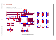
7. Peripheral Schematics
NC3
GPIO12
GPIO14
GND
EN
SENSOR_VP
GPI36
SENSOR_VN
GPI39
GPI34
GPI35
GPIO32
GPIO33
GPIO25
GPIO26
GPIO27
GPIO13
GND
SD2
SD3
CMD
GPIO23
GPIO22
TXD0
RXD0
GPIO21
GPIO19
GPIO18
GPIO4
GPIO0
GPIO5
CLK
SD0
SD1
GPIO15
GPIO2
GND
GPIO14
GPIO12
GPIO13
GPIO15
EN
VDD33
GND GND
GND
GND
VDD33
GND
MTMS
MTDI
MTCK
MTDO
Reset Button
JP2
Boot Option
1
1
2
2
C3
0.1uF/50V(10%)
U1
ESP32_WROVER
GND1
1
3V3
2
EN
3
SENSOR_VP
4
SENSOR_VN
5
IO34
6
IO35
7
IO32
8
IO33
9
IO25
10
IO26
11
IO27
12
IO14
13
IO12
14
GND2
15
IO13
16
SD2
17
SD3
18
CMD
19
CLK
20
SD0
21
SD1
22
IO15
23
IO2
24
IO0
25
IO4
26
NC1
27
NC2
28
IO5
29
IO18
30
IO19
31
NC
32
IO21
33
RXD0
34
TXD0
35
IO22
36
IO23
37
GND3
38
P_GND
39
R2 0R(5%)
SW1
C4 0.1uF/50V(10%)
JP1
UART
1
1
2
2
3
3
4
4
C2
0.1uF/50V(10%)
C1
22uF/25V(10%)
JP3
JTAG
1
1
2
2
3
3
4
4
R1
10K(5%)
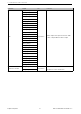
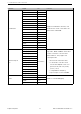
Figure 4: ESP32-WROVER Peripheral Schematics
Note:
• Soldering Pad 39 to the Ground of the base board is not necessary for a satisfactory thermal performance. If users
do want to solder it, they need to ensure that the correct quantity of soldering paste is applied.
• When ESP32 is powered on and off repeatedly by switching the power rails, and there is a large capacitor on
the VDD33 rail, a discharge circuit can be added to the VDD33 rail. Please find details in Chapter Peripheral
Schematics, in ESP-WROOM-32 Datasheet.
Espressif Systems 19 ESP32-WROVER Datasheet V1.2