
User's Manual
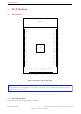
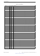
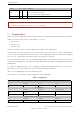
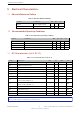
Table Of Contents
2. Pin Definitions
Name No. Type Function
EN 41 I
High: on, enables the chip.
Low: off, the chip powers off.
Note: Do not leave the EN pin floating.
GND 42 P Ground
Notice:
For peripheral pin configurations, please refer to ESP32-S2 User Manual.
2.3 Strapping Pins
ESP32-S2 has three strapping pins: GPIO0, GPIO45, GPIO46. The pin-pin mapping between ESP32-S2 and the
module is as follows, which can be seen in Chapter 5 Schematics:
• GPIO0 = IO0
• GPIO45 = IO45
• GPIO46 = IO46
Software can read the values of corresponding bits from register ”GPIO_STRAPPING”.
During the chip’s system reset (power-on-reset, RTC watchdog reset, brownout reset, analog super watchdog
reset, and crystal clock glitch detection reset), the latches of the strapping pins sample the voltage level as strapping
bits of ”0” or ”1”, and hold these bits until the chip is powered down or shut down.
IO0, IO45 and IO46 are connected to the internal pull-up/pull-down. If they are unconnected or the connected
external circuit is high-impedance, the internal weak pull-up/pull-down will determine the default input level of these
strapping pins.
To change the strapping bit values, users can apply the external pull-down/pull-up resistances, or use the host
MCU’s GPIOs to control the voltage level of these pins when powering on ESP32-S2.
After reset, the strapping pins work as normal-function pins.
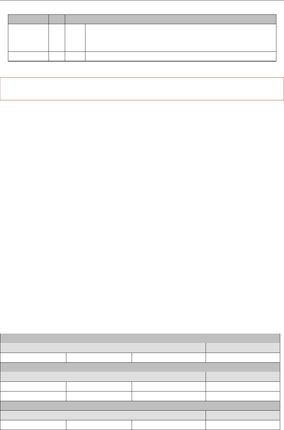
Refer to Table 3 for a detailed boot-mode configuration of the strapping pins.
Table 3: Strapping Pins
VDD_SPI Voltage
1
Pin Default 3.3 V 1.8 V
IO45
2
Pull-down 0 1
Booting Mode
Pin Default SPI Boot Download Boot
IO0 Pull-up 1 0
IO46 Pull-down Don’t-care 0
Enabling/Disabling ROM Code Print During Booting
3 4
Pin Default Enabled Disabled
IO46 Pull-down See the fourth note See the fourth note
Espressif Systems
6
Submit Documentation Feedback
ESP32-S2-WROOM & ESP32-S2-WROOM-I User Manual V0.5