
User's Manual
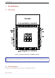
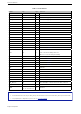
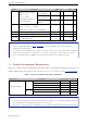
Table Of Contents
- 1 Module Overview
- 3 Pin Definitions
- 4 Electrical Characteristics
- 7 Physical Dimensions and PCB Layout
- 8 Product Handling
- 9 MAC Addresses and eFuse
- 11 Learning Resources
- Revision History
- 空白页面

2.
Pin Definitions
Table 1: Pin Definitions
Name No. Type Function
I34 1 I GPIO34
I35 2 I GPIO35
DBG_RXD/IO3 3 I/O GPIO3, Debugging UART RX
DBG_TXD/IO0 4 I/O GPIO1, Debugging UART TX
IO32 5 I/O GPIO32
IO33 6 I/O GPIO33
IO25 7 I/O GPIO25
IO26 8 I/O GPIO26
MTMS/IO14 9 I/O GPIO14, MTMS
MTDI/IO12 10 I/O GPIO12, MTDI
MTCK/IO13 11 I/O GPIO13, MTCK
MTDO/IO15 13 I/O GPIO15, MTDO
BOOT/IO0 14 I/O GPIO0
IO4 15 I/O GPIO4
IO2 16 I/O GPIO2
IO5 17 I/O GPIO5
IO20 18 I/O GPIO20. See note 1 under the table.
EN 19 I
High: On; enables the module
Low: Off; the module powers off
Note: Do not leave this pin floating.
VDD33 22 P Power supply (3.0 V ~ 3.6 V)
IO9 33 I/O GPIO9. See note 1 under the table.
IO10 34 I/O GPIO10. See note 1 under the table.
IO7 35 I/O GPIO7. See note 1 under the table.
IO8 36 I/O GPIO8. See note 1 under the table.
I36 38 I GPIO36
I37 39 I GPIO37
IO21 40 I/O GPIO21
U1TXD/IO19 41 O UART TX, connected to host RX, GPIO19
VDD33 43 P Power supply (3.0 V ~ 3.6 V)
U1RXD/IO22 45 I UART RX, connected to host TX, GPIO22
I39 46 I GPIO39
INT_B/IO27 47 O Host interrupt, connected to host GPIO, GPIO27
I38 48 I GPIO38
GND
12, 20, 21, 23 ~ 32,
37, 42, 44, 49 ~ 77
P Ground
Note:
1. IO7/IO8/IO9/IO10/IO20 belong to VDD_SDIO power domain and cannot work when VDD_SDIO power shuts down.
2. For peripheral pin configurations, please refer to ESP32User Manual.
Espressif Systems