
User's Manual

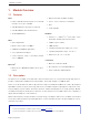
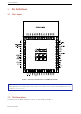
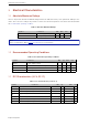
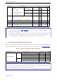
Table Of Contents
- 1 Module Overview
- 3 Pin Definitions
- 4 Electrical Characteristics
- 7 Physical Dimensions and PCB Layout
- 8 Product Handling
- 9 MAC Addresses and eFuse
- 11 Learning Resources
- Revision History
- 空白页面

4. Electrical Characteristics
Symbol Parameter Min Typ Max Unit
I
OH
High-level source current
(VDD
1
= 3.3 V,
V
OH
>= 2.64 V,
output drive strength set
to the maximum)
VDD3P3_CPU
power domain
1, 2
- 40 - mA
VDD3P3_RTC
power domain
1, 2
- 40 - mA
VDD_SDIO power
domain
1, 3
- 20 - mA
I
OL
Low-level sink current
(VDD
1
= 3.3 V, V
OL
= 0.495 V,
output drive strength set to the maximum)
- 28 - mA
R
P U
Resistance of internal pull-up resistor - 45 - kΩ
R
P D
Resistance of internal pull-down resistor - 45 - kΩ
V
IL_nRST
Low-level input voltage of CHIP_PU
to power off the chip
- - 0.6 V
Note:
1.
Please see Appendix IO_MUX of ESP32 User Manual for IO’s power domain. VDD is the I/O voltage for a
particular power domain of pins.
2. For VDD3P3_CPU and VDD3P3_RTC power domain, per-pin current sourced in the same domain is gradually
reduced from around 40 mA to around 29 mA, V
OH
>=2.64 V, as the number of current-source pins increases.
3. Pins occupied by flash and/or PSRAM in the VDD_SDIO power domain were excluded from the test.
3.4 Current Consumption Characteristics
With the use of advanced power-management technologies, ESP32 can switch between different power modes. For
details on different power modes, please refer to Section RTC and Low-Power Management in ESP32 User Manual.
Table 6: Current Consumption Depending on RF Modes
Work mode Description Average (mA) Peak (mA)
Active (RF working)
TX
802.11b, 20 MHz, 1 Mbps
233 368
802.11g, 20 MHz, 54 Mbps
181 258
802.11n, 20 MHz, MCS7
178 248
802.11n, 40 MHz, MCS7
162 205
RX
802.11b/g/n, 20 MHz 110 111
802.11n, 40 MHz 116 117
Note:
• The current consumption measurements are taken with a 3.3 V supply at 25 °C of ambient temperature at the RF
port. All transmitters’ measurements are based on a 50% duty cycle.
• The current consumption figures for in RX mode are for cases when the peripherals are disabled and the CPU idle.
Espressif Systems