
User's Manual


!
1. ESP-PICO-KIT Overview
1.2. Functional Description
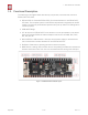
The following list and figure below describe key components, interfaces and controls of
ESP32-PICO-KIT board.
• ESP32-PICO-D4: Standard ESP32-PICO-D4 module soldered to the ESP32-PICO-
KIT board. The complete system of the ESP32 chip has been integrated into the SIP
module, requiring only external filter capacitors and pull-up resistors for EN signals to
function properly.
• USB-UART Bridge:
• I/O: All the pins on ESP32-PICO-D4 are broken out to the pin headers on the board.
Users can program ESP32 to enable multiple functions such as PWM, ADC, DAC,
I2C, I2S, SPI, etc.
• Micro USB Port: USB interface. It functions as the power supply for the board and
the communication interface between PC and ESP32-PICO-KIT.
•
EN Button: Reset button; pressing this button resets the system.
• BOOT Button: Holding down the Boot button and pressing the EN button initiates the
firmware download mode. Then user can download firmware through the serial port.
!
Figure 1-2. ESP32-PICO-KIT Board Layout
Espressif
! /122
2017.11